I bought a green 7-Segment Display w/I2C backpack and a 2.2" color TFT LCD display from Adafruit to experiment with.
|
|


The backpack on the 7 segment display allows it to be controlled by the Arduino using the I2C protocol (also called Two Wire Interface). Without the I2C backpack you would have to directly control all eight segments of each number which would use up all the pins on the Arduino or you would have to figure out some other method which would probably end up being very similar to what Adafruit did. Each Arduino model has certain pins that are used for I2C. On the Uno pins analog 4 and analog 5 are used for this purpose. See the Wire library page for more I2C info.
What is a VSS?
Most modern computer controlled cars since the late 1990's have a sensor called a VSS or Vehicle Speed Sensor. The location of the sensor varies but they all do the same thing which is count the number of times some part of the drive train rotates. On my car the VSS is in the transmission. The output of the VSS is some number of pulses per mile in a 5 vdc square wave signal. The first step in this project was to find out how many pulses per mile my VSS puts out. This number varies from car manufacturer to car manufacturer and sometimes model to model. I found a company that makes aftermarket cruise control systems and their installation manual contained a list of cars and VSS pulses per mile. The pulses per mile value can range from 2000 all the way up to 38600. The VSS on my car puts out 4000 ppm which seems to be a common value but you must find out the correct value for your particular vehicle otherwise the readings will be incorrect. You can also consult their installation manual for the location of the VSS signal wire. It is important that you only tap into the VSS wire and not completely interrupt it. The engine and transmission computers use this signal as well.
Time for some math
So now I know my VSS puts out 4000 pulses per mile. Next I need to figure out how to convert that into miles per hour. After looking at some example code on how to measure pulses I decided I would count the VSS pulses for one second. With that info I could then convert the pulse count into mph. First I converted one hour (the hour from miles per hour) into seconds which is 3600. Then divide the number of pulses per mile by the number of seconds (4000/3600). Then you divide the number of pulses counted on the sensor by that value. Here is my final formula:
miles per hour = pulse count/(VSS pulses per mile/time period)
Building the prototype
I started with an Arduino Uno and an Adafruit Protosheild. I hacked up an old USB cable to connect the 7-segment display. A USB cable is perfect for this. Two wires for the I2C and two larger gauge wires for power and ground. I cut off the ends of the USB cable and stripped each of the wires. I tinned the wires with solder so I could plug them directly into the bread board and added some heat shrink tubing for strain relief. Here is a Fritzing diagram of the wiring:

- Connect 'C' (CLK) on the display to Analog #5. (Leonardo Digital #3, Mega digital #21)
- Connect 'D' (DAT) on the display to Analog #4. (Leonardo Digital #2, Mega digital #20)
- Connect GND on the display to common ground
- Connect VCC+ on the display to power +5V
- VSS sensor on the vehicle connects to Digital #5
- Analog #0 is used to measure a Photocell (Light Dependent Resistor)
Here is how the wiring looks
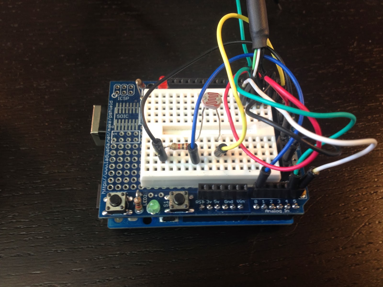

After I tested it at night I decided to add a photocell (Light Dependent Resistor) to control the brightness of the display. It took some tweaking to get the brightness changes just right. Initially the brightness of the display fluctuated with every street light I passed. I changed the code to use an average of 30 light level readings. That way the brightness changes slowly.
Here is how it looks in my car during the day.

and at night

The github repo is here https://github.com/matt448/arduino/tree/master/Speedometer_7seg
The code for the hardware pulse counting section came straight from example 18.7 in the Arduino Cookbook. My understanding of how this works is: the ATmega chip has a few hardware timers. This code uses a timer on Digital #5 on the UNO. The TCCR1B part of the code sets bits on that timer to configure it to count pulses. The code then waits for one second and reads how many pulses were stored in the hardware counter. Then the hardware counter is reset to zero for the next loop. Keep in mind this code is written specifically for an Arduino Uno. It would need to be modified to work with other boards.
Here is the current version of the code in a gist.
I made a quick little cardboard housing for the 7-segment display to shield it from the sun.
After I tested it at night I decided to add a photocell (Light Dependent Resistor) to control the brightness of the display. It took some tweaking to get the brightness changes just right. Initially the brightness of the display fluctuated with every street light I passed. I changed the code to use an average of 30 light level readings. That way the brightness changes slowly.
Here is how it looks in my car during the day.
and at night
The code
The github repo is here https://github.com/matt448/arduino/tree/master/Speedometer_7seg
The code for the hardware pulse counting section came straight from example 18.7 in the Arduino Cookbook. My understanding of how this works is: the ATmega chip has a few hardware timers. This code uses a timer on Digital #5 on the UNO. The TCCR1B part of the code sets bits on that timer to configure it to count pulses. The code then waits for one second and reads how many pulses were stored in the hardware counter. Then the hardware counter is reset to zero for the next loop. Keep in mind this code is written specifically for an Arduino Uno. It would need to be modified to work with other boards.
Here is the current version of the code in a gist.
Results
I tested my new speedometer against the GPS and it was right on the money. It also reacts quite a bit faster than the GPS and it works inside a parking garage unlike the GPS. I have been using it for about a month now and it works great. The only negative I have found is the display isn't readable when the sun is shining directly into it which isn't very often because of the housing. I'm looking into other display options now that I have something that works. VFD displays seem like a good option. I'm also still tinkering with the 2.2" TFT display. Here is a video of the speedometer in actionNext steps
I am planning to solder all the connections on a piece of perfboard that I have turned into a shield of sorts. I'll need to put it in a box and tuck it some where in the dash. Currently I am powering the unit with a 12volt to USB power supply which is plugged into a cigarette lighter jack. I might take that apart and package the guts of the power supply with the Uno.
