Thursday, July 31, 2014

LED light up bicycle

The city of Round Rock, Texas has an annual night time bike ride event at the end of July. It starts at 9pm with a ride through the downtown area to a city park where they have music, free hotdogs and free shaved ice. After the event everyone rides back to the starting point. It sounded like fun to me so I decided I wanted to participate along with my two older kids. As the event approached I started to think it would be fun to decorate my bike for the event. I didn't want to spend much money because this was going to be a pretty temporary thing. I started scrounging my plastic storage bins of electronics for parts. I found a 12 volt LED light strip that had originally been purchased to be used as under cabinet lighting (which I never installed). I had an old unused UPS battery backup that came with our AT&T Uverse service. I tore that UPS open and found a nice 12 amp hour SLA battery. I also had four extra TIP120 transistors and an Arduino Uno. Seemed like enough ingredients to make something cool.

I started by measuring how many amps the full strip of LED's drew at full brightness. It measured 1.3 amps so the battery should give me about 9 hours of run time between charges which is obviously more than enough for a long night ride.

The spool had just enough LED's to light up each of the tubes of the frame on both sides of the bike. The LED strips have a cut line every three LED's. I cut the LED strips into sections that would fit each of the tubes on the frame of my bike.


Then I soldered power and ground leads onto each of the strips and covered the connections with heat shrink.


I attached the LED strips to my bike using zip ties and black electrical tape.


Next I wired up the TIP120 transistors on some scrap proto board. I soldered on a row of right angle headers so I could plug the Arduino right onto the board. Please keep in mind I was just throwing this together at the last minute so it isn't very pretty. The only real goal was to make it fit on top of the battery and stay out of my way while pedaling the bike. I used a scrap barrel connector pigtail for the main power to the board and another to power the Arduino. I added a 12 volt regulator to the Arduino power circuit because the battery was putting out a little over 13 volts and I didn't want to damage the voltage regulator on the Arduino. The transistors connect to four different LED segments and are controlled by four PWM digital pins on the Arduino. I used a different color wire for each transistor and LED segment so I could keep track of them when I wrote the software for animating the segments.


The transistor circuit is very simple. The TIP120 isn't the best way to do this but I had them laying around. A N-channel Power MOSFET is better for this because it can handle high amperage without generating heat. 

Example of TIP120 used with an Arduino.
Image taken from here


I couldn't wait anymore to see what the bike looked like in action so I just taped the battery to the frame and took it out for a quick test ride. At this point the Arduino software just faded the LED's to full brightness and didn't do anything else.


Now I turned my attention to making a proper mount for the battery. I wanted to make sure the battery was mounted solidly so it didn't fall off the bike when I hit a bump. I started with an old L bracket I had laying around the garage and drilled some holes in it so it matched up with the water bottle mounts on the seat post tube of the bike. I bent the L bracket down a bit so the battery would sit level on the bike. Next I took a piece of scrap sheet metal and created a short metal box for the battery to sit in. I made another tab out of sheet metal so the battery box could also bolt to the other water bottle mount on the down tube. I spot welded everything together and ground down the welds on the battery box so it didn't scratch or cut my legs while pedaling.


After the welding and grinding was all done I mounted the battery box on the bike.


I did a test fit of the battery and it was a little loose in the box but I had planned on putting something on the top edge of the sheet metal to cover any sharp edges.


I scrounged around the garage a bit more and found some extra automotive vacuum tubing. I made a slit down the entire length of the vacuum tubing and then pushed it on the top edge of the battery box.


Now the battery fit very snug in the box.


Next I made two velcro straps out of 1" webbing. I cut the webbing to length and sewed on some velcro with the sewing machine. These straps will hold the battery in box.


Here is the battery with the straps in place and then the control board installed on top of the battery.


Here is how the overall bike looks with everything installed.


The last thing I needed was some way to charge the battery. I searched around on Amazon and found this SLA battery charger. I paid about $18 US dollars for it. It has an automatic shutoff once the charging is complete. It only comes with screw terminals so I had to make my own cable. I used yet another barrel connector and some 18 gauge wire to make a cable. (seriously how many barrel connectors can one person have? I may have used up my stockpile on this project.) I triple checked the polarity of the connecters on my charger and my battery with the voltmeter and then charged up the battery.


I finished writing the code for the Arduino the night before the event. Here is a video showing the animations. Since I only had four TIP120 transistors I could only control four sections of the LED's. The fork and the seat tube just stay on full brightness.


Here are my kiddos at the starting line a few hours before the event.


The night ride event was really fun and my kids enjoyed the ride. I'll go ahead say I had the coolest bike at the night ride. This bike has inspired me to get some exercise and I have been riding about 4 miles every night since the event. Maybe for next year's event I will step up to some Adafruit NeoPixels.

Wednesday, June 11, 2014

Ubuntu 14.04 init scripts fail and throw errors


I recently built out my first couple Ubuntu 14.04 servers at work and when my chef scripts tried to run they blew up all over the place. Chef was getting errors when trying to start or restart services like ssh and rsyslog. Looking a little deeper at the errors, Chef was executing init scripts directly and getting back an exit status of 1. For example when Chef tried to restart ssh it was running '/etc/init.d/ssh restart'

That script on Ubuntu 14.04 has no output and exits with a status of 1. I attempted to run the same thing manually from the command line on one of the servers and had the same result, no output and an exit status of 1. I did some searching and found other people are running into this same issue with various other services. I did find the command 'service ssh restart' would do the right thing and not throw an error. Since it seemed like this is an Ubuntu or Debian bug with the start scripts I decided to just modify my Chef scripts to use the service command instead.

By default Chef attempts run the scripts in /etc/init.d when starting and stopping services. The service resource in Chef has some attributes that let you modify how services are started. The attributes start_command, stop_command, restart_command and reload_command let you define an alternate command for these actions. Here are the changes I made to get my Chef scripts working again on Ubuntu 14.04.

Before
service "rsyslog" do
    supports :restart => true
    action [:enable,:start]
end

After
service "rsyslog" do
    restart_command "service rsyslog restart"
    start_command "service rsyslog start"
    supports :restart => true
    action [:enable,:start]
end

This change is backwards compatible with older versions of Ubuntu so I don't have to worry about special casing this just for 14.04 boxes.


[Update 1]
After reading a bit more I'm starting to suspect Ubuntu and/or Debian has purposely deprecated running the scripts in /etc/init.d to force people to use Upstart. Apparently these init scripts have been broken since Ubuntu 13.10.


[Update 2]
@retr0h gave me a cleaner way of accomplishing this:

service "rsyslog" do
  provider Chef::Provider::Service::Upstart
  supports :restart => true
  action [:enable,:start]
end

This does the same thing without having to define each command individually.


[Update 3]
@jtimberman informed me that this problem will be fixed in Chef 11.14. In that version Chef will automatically use Upstart for Ubuntu 13.10 and higher. (Chef support ticket) (Git commit)


Wednesday, April 23, 2014

Gmail messages labeled as sent 'via eigbox.net'

At work I had a user who suddenly started having all her outbound Gmail messages labeled as being sent 'via eigbox.net'. My thoughts immediately jumped to virus or malware. A google search of 'via eigbox.net' returned a bunch forum posts where people were having the exact same problem but I didn't find any info on what could be causing this to happen. The next thing I did was try and find info about the domain name eigbox.net. The whois information showed the owner of the domain name is a company called Endurance International Group. They are the parent company of several different hosting providers including HostGator. The domain eigbox.net doesn't have a website but it appeared the domain is used for a hosted e-mail service. At this point I couldn't rule out a virus but there wasn't anything necessarily suspicious about eigbox.net.
Screenshot showing how messages appeared to recipients.
This person primarily used the native Mac Mail application so the next thing I tested was sending a test message from the Mail application and another test message using the Gmail web interface. I examined the message headers in both messages using the 'Show Original' option in Gmail.
Examination of the headers showed that messages sent from the Mac Mail app were definitely being routed through smtp servers at eigbox.net. Messages sent through the Gmail web interface stayed within Google's network. This information let me focus on the Mail app as the source of the problem. I started combing through the settings in Mail.app. I discovered the user had two e-mail accounts configured. One personal account and another for the company Gmail. Under the Gmail settings (Mail > Preferences > Accounts) I noticed the Gmail smtp server said 'Offline' and the check box labeled 'Use only this server' was not checked.


At this point I audibly exclaimed "Aha!".  What I realized is going on is outbound Gmail messages can't reach Google's SMTP server for some reason and Mail.app is failing back to the SMTP server for the the user's personal e-mail account. Surprisingly the e-mail servers for the personal account allows sending of e-mail with any domain in the from address. Checking the 'Use only this server' box and saving the setting causes mail to get stuck in the outbox. In the end the reason the Gmail SMTP server was offline was because the user changed Gmail passwords. Having 'Use only this server' unchecked allowed Mail.app to seek out another SMTP server. It appears Mac Mail stores the IMAP and SMTP passwords separately. When she changed her Gmail password she updated the IMAP password which allowed her to continue to receive mail but it wasn't very obvious that the SMTP password also needed to be changed. 

To change the SMTP password go to Mail > Preferences > Accounts. Click on the 'Outgoing Mail Server (SMTP)' drop down and select 'Edit SMTP Server List...'

Select 'Edit SMTP Server List...' from the drop down.

Click on the 'Advanced' button and enter the password for the SMTP server.
The user's personal e-mail account is hosted by a company called iPage which does web page and e-mail hosting. iPage uses the eigbox.net domain for it's e-mail. iPage is also part of Endurance International Group. Mystery solved.


Monday, March 17, 2014

Arduino - Using digital potentiometers part 2 (MCP4251)

This is part two in a series of posts about using digital potentiometers with Arduino boards. Part one covered the AD8403 digital pot. This post will go over the MCP4251 from Microchip. The MCP4251 is a dual pot chip with the capability to individually disconnect the terminals of each wiper through software and a hardware shutdown pin that shuts down both wipers simultaneously. Communication with the chip is done over SPI. The chip is available in DIP and surface mount configurations. I bought the DIP version so I could use them on a breadboard. The specific part number I bought is MCP4251-103E/P which is a 10k ohm model with an 8 bit resistor network. The 8 bit versions have 256 possible positions for the wiper which works out to approximately 39 ohms increase in resistance for each wiper position on a 10k ohm model.
Two MCP4251 chips
I began searching for an Arduino software library for these pots. I found two but neither of them fit my needs. They didn't implement any of the TCON functionality which was the main reason I was interested in these pots. Here are links to those libraries if you are interested in trying them out:
   https://github.com/jmalloc/arduino-mcp4xxx and https://github.com/teabot/McpDigitalPot

Since there wasn't a preexisting library that would work for me I began figuring out how to talk to this chip. I started with the Arduino example in File > Examples > SPI > DigitalPotControl. The AD840x and AD520x series pots work right out of the box with this example but the MCP4xxx pots use different memory addresses so I started tweaking the example.

Understanding how to talk to the MCP4251

So lets start with the very basics of how to talk to these pots. Sending a command over SPI requires four steps:
1. Take the slave select pin LOW. This tells the chip to listen for commands.
2. Send the memory address for the item we want to change using SPI. This is the memory address for a wiper or terminal connections. This tells the chip what we want to change.
3. Send the new value for the item we specified in step 2. Wipers on the MCP4251 have 256 possible positions so this would be a decimal number between 0-255 or binary B00000000 - B11111111.
4. Take the slave select pin HIGH. This tells the chip to execute the changes.

The AD8406 covered in part 1 used decimal numbers 0-5 as memory addresses for each of the wipers which was very easy to understand. The MCP4251 doesn't use sequential values so I had to go digging in the data sheet to find the right values. Here is the memory map table from the data sheet:


Looking at the data sheet you can see the memory address and the data is made up of a total of 16 bits. The sheet says the data is 10 bits and the memory address is 6 bits but in practice you can send the data in two 8 bit chunks which allows you to use the 'B' binary formatter. The maximum possible value for a wiper is 255 which would be B11111111 in binary. So here is the list of memory addresses and tcon values I was able to determine:

wiper0writeAddr = B00000000;
wiper1writeAddr = B00010000;
  tconwriteAddr = B01000000;
  tcon_0off_1on = B11110000;
  tcon_0on_1off = B00001111;
 tcon_0off_1off = B00000000;
   tcon_0on_1on = B11111111;

The Wiring

Now that I had memory addresses figured out I wired up the digital pot on a breadboard with some LED's. I'm using LED's in this example because it's a good way to visualize the pots changing resistance values. I wired the shutdown pin to a 4.7k pull down resistor so the pot would go into shutdown mode if digital pin 7 wasn't HIGH. My example code also uses the software disconnects (TCON) to turn the LED's off and on.

The connections are:
* All A pins of MCP4251 connected to +5V
* All B pins of MCP4251 connected to ground
* An LED and a 220-ohm resistor in series connected from each W pin to ground
* VSS - to GND
* VDD - to +5v
* SHDN - to digital pin 7 and a 4.7k pull down resistor
* CS - to digital pin 10 (SS pin)
* SDI - to digital pin 11 (MOSI pin)
* SDO - to digital pin 12 (MISO pin)
* CLK - to digital pin 13 (SCK pin)


You can download the fritzing file here:
https://github.com/matt448/arduino/raw/master/MCP4251_tcon/MCP4251_tcon.fzz

and you can download the MCP4251 fritzing part I made here:
https://github.com/matt448/arduino/raw/master/MCP4251_tcon/MCP4251.fzpz


The code

Here is a Gist with the example code. The most recent version will be my the github repo here:
https://github.com/matt448/arduino/tree/master/MCP4251_tcon


Up next

Part 3 in my series of digital potentiometer posts will cover reading data from the MCP4251 to determine the wiper positions and the tcon status. Part 4 will cover using multiple SPI digital potentiometers. I will add a links here as I complete those posts.

Sunday, March 2, 2014

Adding MOLLE / PALS webbing to a backpack

I really like my North Face Surge backpack but I have never found the vertical daisy chain loops on the back panel to be very useful. I guess you can clip on small items with a carabiner but I never do that. I do have a few items that use the MOLLE or PALS attachment system and I would like to attach those to the back panel of my pack. So I decided to try and modify my backpack.

Here is a how the pack looked before I modified it.


The loops down the center of the flap are what I want to change. These vertical loops are usually referred to as a daisy chain. MOLLE, or more specifically PALS, is method of attaching pouches and equipment to a bag. It is used by the military and law enforcement personnel to attach things like radios, ammo clips, knives, first aid kits, etc to bags and vests. There are quite a few handy generic pouches as well. The PALS system uses one inch webbing spaced in horizontal rows one inch apart and sewn at one and half inch intervals. Most people seem to use the term MOLLE and PALS interchangeably but really MOLLE is a line of military gear that uses the PALS attachment system. Equipment that is attached using PALS webbing uses straps that are woven in and out of the rows and secured with a snap or velcro. Some equipment uses plastic clips that hook into the rows.

Here is a diagram of how to sew PALS / MOLLE.


Before I modified my backpack I first tried sewing some PALS webbing onto scrap fabric.


It went pretty well on the scrap fabric. The ends of the webbing were a little difficult because had melted them a little too much. When cutting the webbing you need to use a flame to melt the ends to keep it from fraying but it only needs to be melted very lightly. If you melt it too much it will cause big lumps which are difficult to sew. I did a test fit of my Leatherman sheath and it fit perfectly so I moved on to modifying my backpack.

The first step was to run a zigzag stitch across the rubbery material to hold it in place and to reinforce the strap before I shortened it. Then I used a seam ripper to remove all the stitching below the zigzag stitch. After that I used some scissors to cut off the strap and rubbery material from the area I want to place rows of PALS webbing.


Next I laid out the rows of webbing. I started out with laying pieces of webbing on the bag and measuring but it was difficult to visualize where the loops would end up. I made a paper diagram which made it easier to see how many full loops I could get. Because the flap tapers up I was only able to get three loops but that would be perfect for attaching my Leatherman and a flash light. Next I used a water soluble marking pencil to lay out the webbing and sewing line locations.


I trimmed the ends of the webbing to the same taper as the flap and lightly melted the ends. Then I pinned the webbing in place.


Next up was the sewing. The top piece of webbing wasn't too bad but the lower piece took some acrobatics to get all the lines sewn. I ran a straight stitch first and then a zigzag stitch over top of it for strength.


Sewing is complete. The stitching is visible on the inside of the flap but it doesn't look too terrible and the flap is usually closed. Quick test fit of my Leatherman and then all that's left is to clean up the white pencil lines with a washcloth and some water.


And here is the finished product. It turned out exactly like wanted. :-)


[UPDATE 2014-07-31]

Just a small update. I sewed my own MOLLE flashlight holder out of some 2" webbing and added that to my pack. My buddy bought me a 'tactical' pen which fits nicely on the center loops.


Monday, February 3, 2014

Arduino - Digital speedometer

I have all aftermarket gauges in my car and a while ago my aftermarket speedometer died. The needle just dropped to zero while I was driving down the highway. Since then I have been using my Garmin GPS as my speedometer but it's maps are really out of date and I actually prefer to use Waze on my iPhone for navigation. I wanted to ditch the Garmin but then I wouldn't have a speedometer. I thought it might be fun project to try and build a cheap speedometer using an Arduino Uno and some type of digital display.

I bought a green 7-Segment Display w/I2C backpack and a 2.2" color TFT LCD display from Adafruit to experiment with.

7-Segment

2.2" TFT Display

After playing with both displays I found the TFT display couldn't refresh fast enough. (actually I just don't know how to make it refresh fast enough). The redraw on the TFT made the numbers flash which was very annoying. I may use the TFT screen to show other info that doesn't have to be refreshed frequently like average speed and trip distance. The 7-Segment worked well so I focused on using it. The Adafruit LED Backpack library for the 7-Segment display is pretty easy to use. Writing numbers to the 7 Segment display is nearly as simple as a Serial.print. The only issue I ran into was controlling the brightness. The brightness function in their library didn't work for me. I end up looking at the code in their library wrote my own function.

The backpack on the 7 segment display allows it to be controlled by the Arduino using the I2C protocol (also called Two Wire Interface). Without the I2C backpack you would have to directly control all eight segments of each number which would use up all the pins on the Arduino or you would have to figure out some other method which would probably end up being very similar to what Adafruit did. Each Arduino model has certain pins that are used for I2C. On the Uno pins analog 4 and analog 5 are used for this purpose. See the Wire library page for more I2C info.


What is a VSS?


Most modern computer controlled cars since the late 1990's have a sensor called a VSS or Vehicle Speed Sensor. The location of the sensor varies but they all do the same thing which is count the number of times some part of the drive train rotates. On my car the VSS is in the transmission. The output of the VSS is some number of pulses per mile in a 5 vdc square wave signal. The first step in this project was to find out how many pulses per mile my VSS puts out. This number varies from car manufacturer to car manufacturer and sometimes model to model. I found a company that makes aftermarket cruise control systems and their installation manual contained a list of cars and VSS pulses per mile. The pulses per mile value can range from 2000 all the way up to 38600. The VSS on my car puts out 4000 ppm which seems to be a common value but you must find out the correct value for your particular vehicle otherwise the readings will be incorrect. You can also consult their installation manual for the location of the VSS signal wire. It is important that you only tap into the VSS wire and not completely interrupt it. The engine and transmission computers use this signal as well.


Time for some math


So now I know my VSS puts out 4000 pulses per mile. Next I need to figure out how to convert that into miles per hour. After looking at some example code on how to measure pulses I decided I would count the VSS pulses for one second. With that info I could then convert the pulse count into mph. First I converted one hour (the hour from miles per hour) into seconds which is 3600. Then divide the number of pulses per mile by the number of seconds (4000/3600). Then you divide the number of pulses counted on the sensor by that value. Here is my final formula:

miles per hour = pulse count/(VSS pulses per mile/time period)


Building the prototype


I started with an Arduino Uno and an Adafruit Protosheild. I hacked up an old USB cable to connect the 7-segment display. A USB cable is perfect for this. Two wires for the I2C and two larger gauge wires for power and ground. I cut off the ends of the USB cable and stripped each of the wires. I tinned the wires with solder so I could plug them directly into the bread board and added some heat shrink tubing for strain relief. Here is a Fritzing diagram of the wiring:


- Connect 'C' (CLK) on the display to Analog #5. (Leonardo Digital #3, Mega digital #21)
- Connect 'D' (DAT) on the display to Analog #4. (Leonardo Digital #2, Mega digital #20)
- Connect GND on the display to common ground
- Connect VCC+ on the display to power +5V
- VSS sensor on the vehicle connects to Digital #5
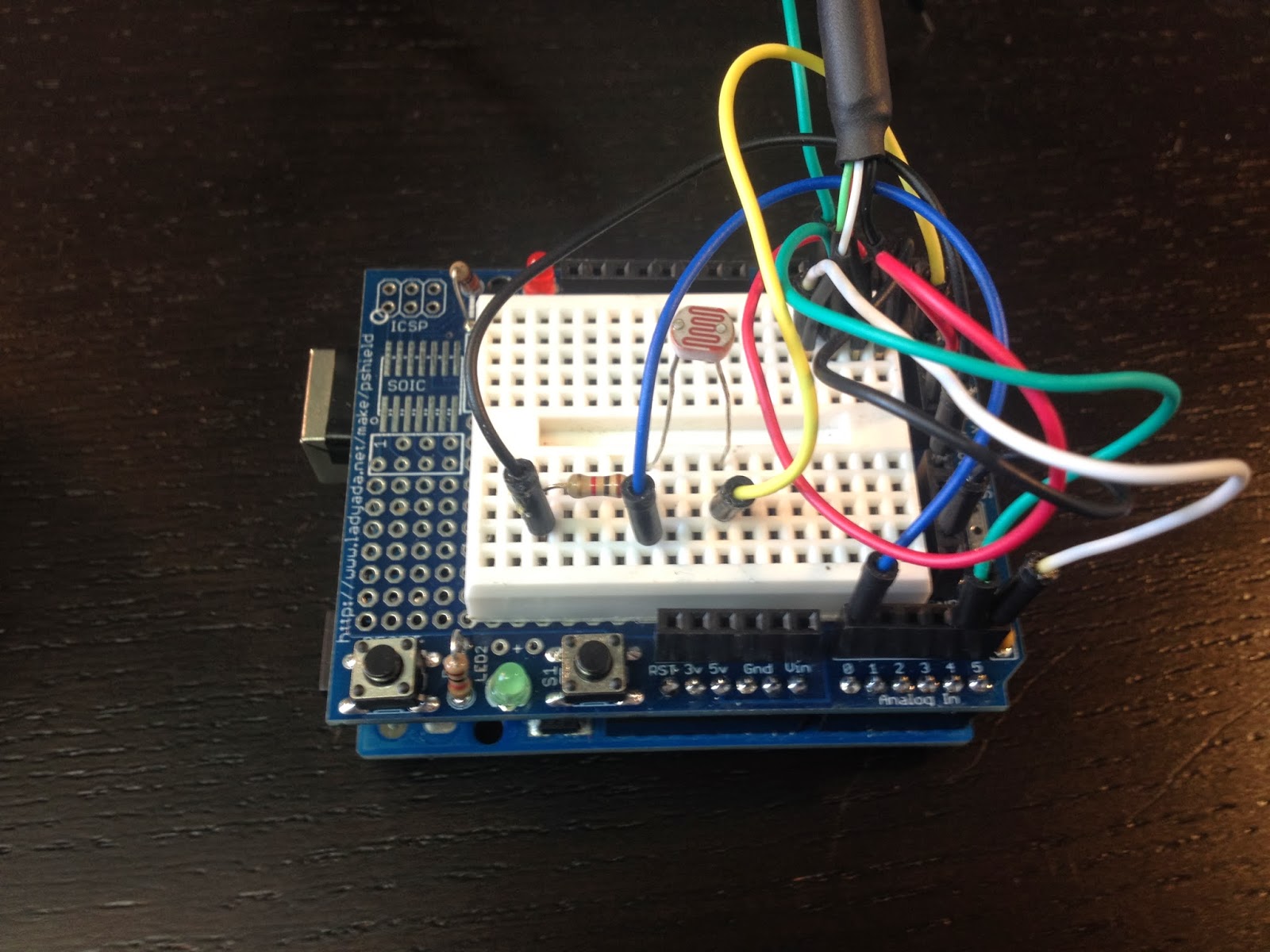
- Analog #0 is used to measure a Photocell (Light Dependent Resistor)

Here is how the wiring looks

I made a quick little cardboard housing for the 7-segment display to shield it from the sun.

After I tested it at night I decided to add a photocell (Light Dependent Resistor) to control the brightness of the display. It took some tweaking to get the brightness changes just right. Initially the brightness of the display fluctuated with every street light I passed. I changed the code to use an average of 30 light level readings. That way the brightness changes slowly.

Here is how it looks in my car during the day.

and at night

The code


The github repo is here https://github.com/matt448/arduino/tree/master/Speedometer_7seg
The code for the hardware pulse counting section came straight from example 18.7 in the Arduino Cookbook. My understanding of how this works is: the ATmega chip has a few hardware timers. This code uses a timer on Digital #5 on the UNO. The TCCR1B part of the code sets bits on that timer to configure it to count pulses. The code then waits for one second and reads how many pulses were stored in the hardware counter. Then the hardware counter is reset to zero for the next loop. Keep in mind this code is written specifically for an Arduino Uno. It would need to be modified to work with other boards.

Here is the current version of the code in a gist.


Results

I tested my new speedometer against the GPS and it was right on the money. It also reacts quite a bit faster than the GPS and it works inside a parking garage unlike the GPS. I have been using it for about a month now and it works great. The only negative I have found is the display isn't readable when the sun is shining directly into it which isn't very often because of the housing. I'm looking into other display options now that I have something that works. VFD displays seem like a good option. I'm also still tinkering with the 2.2" TFT display. Here is a video of the speedometer in action


Next steps

I am planning to solder all the connections on a piece of perfboard that I have turned into a shield of sorts. I'll need to put it in a box and tuck it some where in the dash. Currently I am powering the unit with a 12volt to USB power supply which is plugged into a cigarette lighter jack. I might take that apart and package the guts of the power supply with the Uno.