Monday, March 17, 2014

Arduino - Using digital potentiometers part 2 (MCP4251)

This is part two in a series of posts about using digital potentiometers with Arduino boards. Part one covered the AD8403 digital pot. This post will go over the MCP4251 from Microchip. The MCP4251 is a dual pot chip with the capability to individually disconnect the terminals of each wiper through software and a hardware shutdown pin that shuts down both wipers simultaneously. Communication with the chip is done over SPI. The chip is available in DIP and surface mount configurations. I bought the DIP version so I could use them on a breadboard. The specific part number I bought is MCP4251-103E/P which is a 10k ohm model with an 8 bit resistor network. The 8 bit versions have 256 possible positions for the wiper which works out to approximately 39 ohms increase in resistance for each wiper position on a 10k ohm model.
Two MCP4251 chips
I began searching for an Arduino software library for these pots. I found two but neither of them fit my needs. They didn't implement any of the TCON functionality which was the main reason I was interested in these pots. Here are links to those libraries if you are interested in trying them out:
   https://github.com/jmalloc/arduino-mcp4xxx and https://github.com/teabot/McpDigitalPot

Since there wasn't a preexisting library that would work for me I began figuring out how to talk to this chip. I started with the Arduino example in File > Examples > SPI > DigitalPotControl. The AD840x and AD520x series pots work right out of the box with this example but the MCP4xxx pots use different memory addresses so I started tweaking the example.

Understanding how to talk to the MCP4251

So lets start with the very basics of how to talk to these pots. Sending a command over SPI requires four steps:
1. Take the slave select pin LOW. This tells the chip to listen for commands.
2. Send the memory address for the item we want to change using SPI. This is the memory address for a wiper or terminal connections. This tells the chip what we want to change.
3. Send the new value for the item we specified in step 2. Wipers on the MCP4251 have 256 possible positions so this would be a decimal number between 0-255 or binary B00000000 - B11111111.
4. Take the slave select pin HIGH. This tells the chip to execute the changes.

The AD8406 covered in part 1 used decimal numbers 0-5 as memory addresses for each of the wipers which was very easy to understand. The MCP4251 doesn't use sequential values so I had to go digging in the data sheet to find the right values. Here is the memory map table from the data sheet:


Looking at the data sheet you can see the memory address and the data is made up of a total of 16 bits. The sheet says the data is 10 bits and the memory address is 6 bits but in practice you can send the data in two 8 bit chunks which allows you to use the 'B' binary formatter. The maximum possible value for a wiper is 255 which would be B11111111 in binary. So here is the list of memory addresses and tcon values I was able to determine:

wiper0writeAddr = B00000000;
wiper1writeAddr = B00010000;
  tconwriteAddr = B01000000;
  tcon_0off_1on = B11110000;
  tcon_0on_1off = B00001111;
 tcon_0off_1off = B00000000;
   tcon_0on_1on = B11111111;
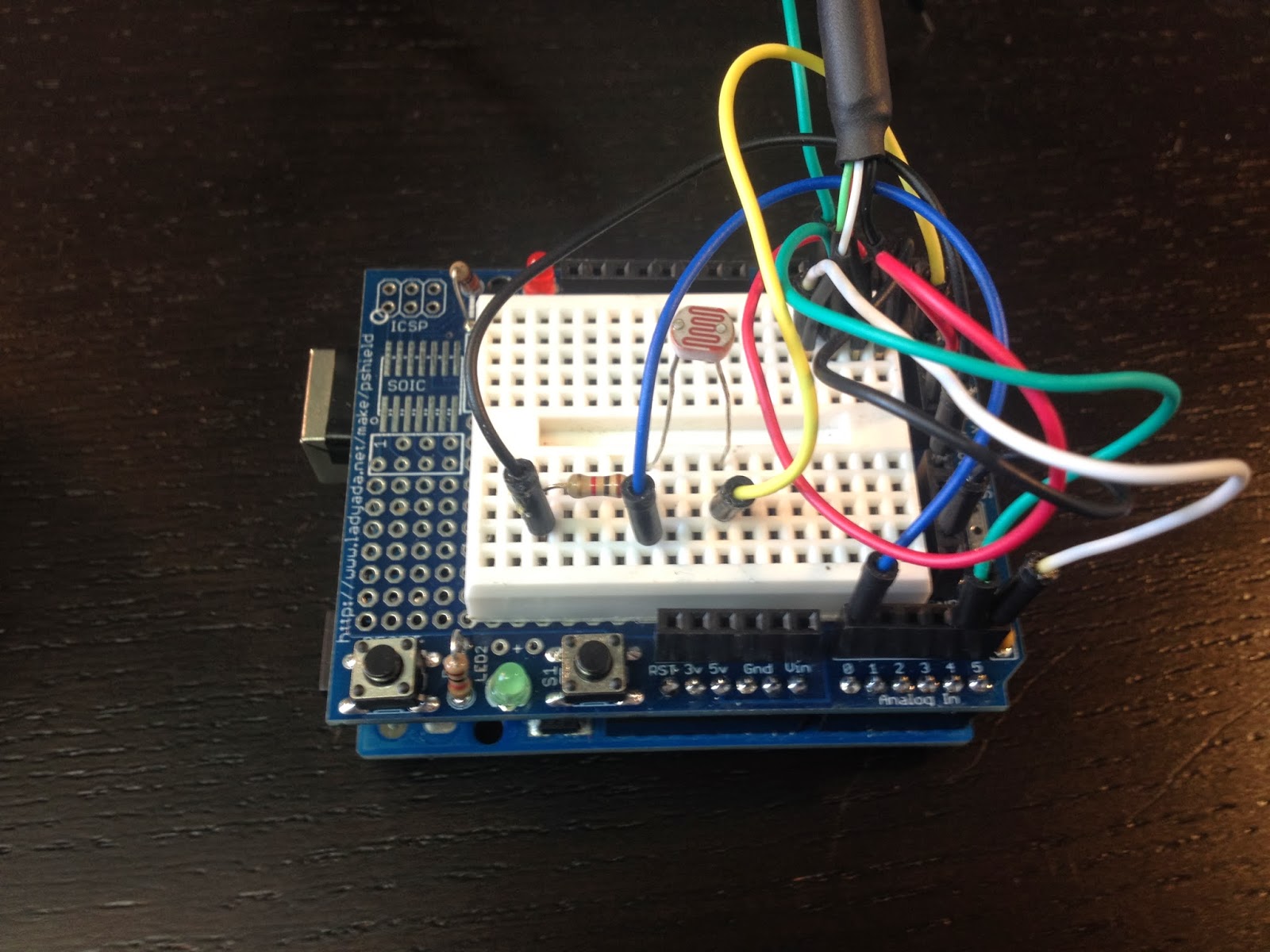
The Wiring

Now that I had memory addresses figured out I wired up the digital pot on a breadboard with some LED's. I'm using LED's in this example because it's a good way to visualize the pots changing resistance values. I wired the shutdown pin to a 4.7k pull down resistor so the pot would go into shutdown mode if digital pin 7 wasn't HIGH. My example code also uses the software disconnects (TCON) to turn the LED's off and on.

The connections are:
* All A pins of MCP4251 connected to +5V
* All B pins of MCP4251 connected to ground
* An LED and a 220-ohm resistor in series connected from each W pin to ground
* VSS - to GND
* VDD - to +5v
* SHDN - to digital pin 7 and a 4.7k pull down resistor
* CS - to digital pin 10 (SS pin)
* SDI - to digital pin 11 (MOSI pin)
* SDO - to digital pin 12 (MISO pin)
* CLK - to digital pin 13 (SCK pin)


You can download the fritzing file here:
https://github.com/matt448/arduino/raw/master/MCP4251_tcon/MCP4251_tcon.fzz

and you can download the MCP4251 fritzing part I made here:
https://github.com/matt448/arduino/raw/master/MCP4251_tcon/MCP4251.fzpz


The code

Here is a Gist with the example code. The most recent version will be my the github repo here:
https://github.com/matt448/arduino/tree/master/MCP4251_tcon


Up next

Part 3 in my series of digital potentiometer posts will cover reading data from the MCP4251 to determine the wiper positions and the tcon status. Part 4 will cover using multiple SPI digital potentiometers. I will add a links here as I complete those posts.

Sunday, March 2, 2014

Adding MOLLE / PALS webbing to a backpack

I really like my North Face Surge backpack but I have never found the vertical daisy chain loops on the back panel to be very useful. I guess you can clip on small items with a carabiner but I never do that. I do have a few items that use the MOLLE or PALS attachment system and I would like to attach those to the back panel of my pack. So I decided to try and modify my backpack.

Here is a how the pack looked before I modified it.


The loops down the center of the flap are what I want to change. These vertical loops are usually referred to as a daisy chain. MOLLE, or more specifically PALS, is method of attaching pouches and equipment to a bag. It is used by the military and law enforcement personnel to attach things like radios, ammo clips, knives, first aid kits, etc to bags and vests. There are quite a few handy generic pouches as well. The PALS system uses one inch webbing spaced in horizontal rows one inch apart and sewn at one and half inch intervals. Most people seem to use the term MOLLE and PALS interchangeably but really MOLLE is a line of military gear that uses the PALS attachment system. Equipment that is attached using PALS webbing uses straps that are woven in and out of the rows and secured with a snap or velcro. Some equipment uses plastic clips that hook into the rows.

Here is a diagram of how to sew PALS / MOLLE.


Before I modified my backpack I first tried sewing some PALS webbing onto scrap fabric.


It went pretty well on the scrap fabric. The ends of the webbing were a little difficult because had melted them a little too much. When cutting the webbing you need to use a flame to melt the ends to keep it from fraying but it only needs to be melted very lightly. If you melt it too much it will cause big lumps which are difficult to sew. I did a test fit of my Leatherman sheath and it fit perfectly so I moved on to modifying my backpack.

The first step was to run a zigzag stitch across the rubbery material to hold it in place and to reinforce the strap before I shortened it. Then I used a seam ripper to remove all the stitching below the zigzag stitch. After that I used some scissors to cut off the strap and rubbery material from the area I want to place rows of PALS webbing.


Next I laid out the rows of webbing. I started out with laying pieces of webbing on the bag and measuring but it was difficult to visualize where the loops would end up. I made a paper diagram which made it easier to see how many full loops I could get. Because the flap tapers up I was only able to get three loops but that would be perfect for attaching my Leatherman and a flash light. Next I used a water soluble marking pencil to lay out the webbing and sewing line locations.


I trimmed the ends of the webbing to the same taper as the flap and lightly melted the ends. Then I pinned the webbing in place.


Next up was the sewing. The top piece of webbing wasn't too bad but the lower piece took some acrobatics to get all the lines sewn. I ran a straight stitch first and then a zigzag stitch over top of it for strength.


Sewing is complete. The stitching is visible on the inside of the flap but it doesn't look too terrible and the flap is usually closed. Quick test fit of my Leatherman and then all that's left is to clean up the white pencil lines with a washcloth and some water.


And here is the finished product. It turned out exactly like wanted. :-)


[UPDATE 2014-07-31]

Just a small update. I sewed my own MOLLE flashlight holder out of some 2" webbing and added that to my pack. My buddy bought me a 'tactical' pen which fits nicely on the center loops.


Monday, February 3, 2014

Arduino - Digital speedometer

I have all aftermarket gauges in my car and a while ago my aftermarket speedometer died. The needle just dropped to zero while I was driving down the highway. Since then I have been using my Garmin GPS as my speedometer but it's maps are really out of date and I actually prefer to use Waze on my iPhone for navigation. I wanted to ditch the Garmin but then I wouldn't have a speedometer. I thought it might be fun project to try and build a cheap speedometer using an Arduino Uno and some type of digital display.

I bought a green 7-Segment Display w/I2C backpack and a 2.2" color TFT LCD display from Adafruit to experiment with.

7-Segment

2.2" TFT Display

After playing with both displays I found the TFT display couldn't refresh fast enough. (actually I just don't know how to make it refresh fast enough). The redraw on the TFT made the numbers flash which was very annoying. I may use the TFT screen to show other info that doesn't have to be refreshed frequently like average speed and trip distance. The 7-Segment worked well so I focused on using it. The Adafruit LED Backpack library for the 7-Segment display is pretty easy to use. Writing numbers to the 7 Segment display is nearly as simple as a Serial.print. The only issue I ran into was controlling the brightness. The brightness function in their library didn't work for me. I end up looking at the code in their library wrote my own function.

The backpack on the 7 segment display allows it to be controlled by the Arduino using the I2C protocol (also called Two Wire Interface). Without the I2C backpack you would have to directly control all eight segments of each number which would use up all the pins on the Arduino or you would have to figure out some other method which would probably end up being very similar to what Adafruit did. Each Arduino model has certain pins that are used for I2C. On the Uno pins analog 4 and analog 5 are used for this purpose. See the Wire library page for more I2C info.


What is a VSS?


Most modern computer controlled cars since the late 1990's have a sensor called a VSS or Vehicle Speed Sensor. The location of the sensor varies but they all do the same thing which is count the number of times some part of the drive train rotates. On my car the VSS is in the transmission. The output of the VSS is some number of pulses per mile in a 5 vdc square wave signal. The first step in this project was to find out how many pulses per mile my VSS puts out. This number varies from car manufacturer to car manufacturer and sometimes model to model. I found a company that makes aftermarket cruise control systems and their installation manual contained a list of cars and VSS pulses per mile. The pulses per mile value can range from 2000 all the way up to 38600. The VSS on my car puts out 4000 ppm which seems to be a common value but you must find out the correct value for your particular vehicle otherwise the readings will be incorrect. You can also consult their installation manual for the location of the VSS signal wire. It is important that you only tap into the VSS wire and not completely interrupt it. The engine and transmission computers use this signal as well.


Time for some math


So now I know my VSS puts out 4000 pulses per mile. Next I need to figure out how to convert that into miles per hour. After looking at some example code on how to measure pulses I decided I would count the VSS pulses for one second. With that info I could then convert the pulse count into mph. First I converted one hour (the hour from miles per hour) into seconds which is 3600. Then divide the number of pulses per mile by the number of seconds (4000/3600). Then you divide the number of pulses counted on the sensor by that value. Here is my final formula:

miles per hour = pulse count/(VSS pulses per mile/time period)


Building the prototype


I started with an Arduino Uno and an Adafruit Protosheild. I hacked up an old USB cable to connect the 7-segment display. A USB cable is perfect for this. Two wires for the I2C and two larger gauge wires for power and ground. I cut off the ends of the USB cable and stripped each of the wires. I tinned the wires with solder so I could plug them directly into the bread board and added some heat shrink tubing for strain relief. Here is a Fritzing diagram of the wiring:


- Connect 'C' (CLK) on the display to Analog #5. (Leonardo Digital #3, Mega digital #21)
- Connect 'D' (DAT) on the display to Analog #4. (Leonardo Digital #2, Mega digital #20)
- Connect GND on the display to common ground
- Connect VCC+ on the display to power +5V
- VSS sensor on the vehicle connects to Digital #5
- Analog #0 is used to measure a Photocell (Light Dependent Resistor)

Here is how the wiring looks

I made a quick little cardboard housing for the 7-segment display to shield it from the sun.

After I tested it at night I decided to add a photocell (Light Dependent Resistor) to control the brightness of the display. It took some tweaking to get the brightness changes just right. Initially the brightness of the display fluctuated with every street light I passed. I changed the code to use an average of 30 light level readings. That way the brightness changes slowly.

Here is how it looks in my car during the day.

and at night

The code


The github repo is here https://github.com/matt448/arduino/tree/master/Speedometer_7seg
The code for the hardware pulse counting section came straight from example 18.7 in the Arduino Cookbook. My understanding of how this works is: the ATmega chip has a few hardware timers. This code uses a timer on Digital #5 on the UNO. The TCCR1B part of the code sets bits on that timer to configure it to count pulses. The code then waits for one second and reads how many pulses were stored in the hardware counter. Then the hardware counter is reset to zero for the next loop. Keep in mind this code is written specifically for an Arduino Uno. It would need to be modified to work with other boards.

Here is the current version of the code in a gist.


Results

I tested my new speedometer against the GPS and it was right on the money. It also reacts quite a bit faster than the GPS and it works inside a parking garage unlike the GPS. I have been using it for about a month now and it works great. The only negative I have found is the display isn't readable when the sun is shining directly into it which isn't very often because of the housing. I'm looking into other display options now that I have something that works. VFD displays seem like a good option. I'm also still tinkering with the 2.2" TFT display. Here is a video of the speedometer in action


Next steps

I am planning to solder all the connections on a piece of perfboard that I have turned into a shield of sorts. I'll need to put it in a box and tuck it some where in the dash. Currently I am powering the unit with a 12volt to USB power supply which is plugged into a cigarette lighter jack. I might take that apart and package the guts of the power supply with the Uno.


Wednesday, January 15, 2014

Arduino - Improving refresh rate of a TFT LCD display

I'm working on a digital speedometer project for my car and I ordered a couple different displays from Adafruit to experiment with. One of the displays I ordered is a 2.2" color TFT LCD display. I was really hoping to use this display to show the current speed of my car. One concern I had about using it for that purpose was the speed that an Arduino board could refresh the information on the screen. To test the display I wrote a simple sketch that just displays the number of seconds since start. Here is a video of that first attempt:


The redraw time causes the numbers to look like they are flashing which is very annoying. The mistake I made was blanking out the entire screen with tft.fillScreen(ILI9340_BLACK). It takes quite a while to redraw the entire screen with black.

Next I tried drawing a black rectangle just on the area of the screen where I was drawing numbers. Here is the result:


Huge improvement. Only blanking out that small area greatly sped up the redraw time.
In this next video I have highlighted the redraw area in red to make it easier to see what I am talking about:


What I am realizing at this point is you should only redraw information that has changed. If you watch the last video again, once the number goes past single digits the left digit looks like it is flashing. This is because it is being blanked out and redrawn every time the number changes. When you redraw something that hasn't changed it looks like flashing. Well that's it for now. I am going to continue to work on this more and figure out how to selectively redraw only digits that change. Once I figure that out I'll write up another blog post.
[UPDATE] - Here is part two:
 http://matthewcmcmillan.blogspot.com/2014/08/arduino-tft-lcd-display-refresh-rate-part2.html


Here is the code I was using to do my testing.


[Updated 2014-08-08 - Added link to part 2 of this topic]


Saturday, January 11, 2014

Daemonized rvm ruby tasks using start-stop-daemon

I am very new to Ruby so the solution described in this post might be very obvious to some but I could not find all the parts of this solution in one place. I cobbled together bits and pieces of other peoples startup and capistrano scripts to get this working. My research has also shown there are ruby gems that might handle some of this better but I wasn't trying to reinvent the wheel. Anyhow, on with the show. At work, during our capistrano deployment we have a ruby process that has to be launched in the background. We are using start-stop-daemon to daemonize the process but our use of rvm complicates running rake because the rake binary is stored in the .rvm/gems directory. Normally the path to the rake binary is set from .bashrc and .bash_profile when you log in through a shell but when you execute things from cron, start-up scripts or other non-shell environments the paths don't exist. After some googling and tinkering I finally got something that worked:

task :start_mytask, :roles => :mytask, :except => { :no_release => true } do
  run "RAILS_ENV=#{rails_env} start-stop-daemon --start -b -m -o -d ~/current -p ~/pids/mytask.pid -a /home/ubuntu/.rvm/gems/ruby-1.9.3-p194@global/bin/rake mytask"
end

The downside with this script is I was calling rake for a specific version of ruby. At the time this was good enough to get us by. Fast forward several months and now we are preparing to upgrade to ruby 2.0. Our existing start script needed to be updated to use ruby 2.0 but I wanted to find a better way that wouldn't need to be tweaked each time we upgrade ruby. My first shot at updating the script I switched to executing rvm and calling 'bundle exec rake':

task :start_mytask, :roles => :mytask, :except => { :no_release => true } do
   run "RAILS_ENV=#{rails_env} start-stop-daemon --start -b -m -o --chdir ~/current --pidfile ~/pids/mytask.pid --exec ~/.rvm/bin/rvm -- current do bundle exec rake mytask"
end

This eliminates directly calling rake for a specific version of ruby but introduces a different issue. Executing it this way causes rvm to launch in a bash shell which then executes the rake task. start-stop-daemon creates a pid file based off of the first process started which is the bash process not the rake task. So when you try to stop it start-stop-daemon tries to kill the bash process which won't end because it has a child process running the rake task. I was getting closer but it wasn't perfect. More googling ensued and I discovered I could use rvm-exec instead of rvm. The rvm-exec command fixes the bash shell problem. It was created specifically for calling rvm in scripts. Here is what I finally came up with:

task :start_mytask, :roles => :mytask, :except => { :no_release => true } do
  run "RAILS_ENV=#{rails_env} start-stop-daemon --start -b -m -o --chdir ~/current --pidfile ~/pids/mytask.pid --exec ~/.rvm/bin/rvm-exec -- current bundle exec rake mytask"
end

It will now run independent of a ruby version number and since only one process is launched the pid file is created correctly. One other benefit I realized is now it is much easier to monitor this process. Previously the process was listed as just "rake". If you have more than one running that would get tricky to monitor. Launching it with this new script the process is listed as "rake mytask".

Finally to stop the daemonized rake task run this command:

task :stop_mytask, :roles => :mytask, :except => { :no_release => true } do
   run "start-stop-daemon -o -p ~/pids/mytask.pid --stop"
end


[UPDATE 01/13/2014] I realized today after doing more testing that I should be calling 'current bundle exec rake' instead of 'default bundle exec rake'. When you are upgrading ruby versions it doesn't necessarily mean you want to change the default ruby version in rvm. Using 'current' will cause the script to use whatever ruby is specified in the .rvmrc. I have edited the above scripts to reflect my new findings.

Tuesday, December 31, 2013

Simple way to integrate Nagios with Slack messaging

At work we recently switched messaging applications from Skype to a new platform called Slack. Slack just launched in August 2013. I have read it is similar to Campfire but I've never used that platform so I can't really comment on that but it is much more useful than a basic chat client like Skype. With Slack you can share files, easily search message history for text or files and integrate with 3rd party applications. Plus it is private for just your team or company. Slack has quite a few preconfigured integrations plus the ability to create your own custom integrations. First we setup the Github integration which allows all of our commit messages to dump into a channel. Next we setup the Trello integration to dump card changes from our main board into another channel. Then I went to setup the Nagios integration and ran into problems. They have a prebuilt integration for Nagios but I could not get it to work. It would post alert messages into the channel but the messages contained no information:


I mucked with their provided perl script quite a bit but I simply could not get it to work. It just kept posting empty messages. Being impatient and a do-it-yourselfer I set about trying to find another way to accomplish this. I looked through the list of integrations and noticed that they had a custom one called Incoming WebHooks which is an easy way to get messages from external sources posted into Slack. The simplest way to utilize Incoming WebHooks is to use curl to post the message to Slack's API. I wrote a little bash script that provides a detailed Nagios alert, a link back to the Nagios web page and conditional emoji's! Each warning level (OK, WARNING, CRITICAL and UNKNOWN) has it's own emoji icon. Here are some example messages in my Slack client:


Here is my bash script that posts to Slack. I placed it in /usr/local/bin

Here are the Nagios config lines that are added to commands.cfg

And finally lines I added to contacts.cfg

I'm not sure why Slack's prebuilt Nagios integration didn't work for me but I really like what I came up with. No Perl modules to install and the only outside dependency is curl. It's also pretty easy to modify the info in the alert message by adding or removing NAGIOS_ env variables in the curl statement.

Monday, November 4, 2013

Upgrading existing Solr installation to new version of Jetty

At work we have been running into a problem with Apache Solr crashing. Depending on how much it was used we would get several weeks of usage out of it before it crashed. Now it is only running for five days at a time. So this fire has started burning hot enough to be at the top of my to-do list.
When it crashes it throws errors saying "Too many open files". Running lsof showed it wasn't actually open files but thousands of orphaned sockets left open. The sockets looked like this in the lsof output:

java 2428 root 2173u sock 0,7 0t0 123291433 can't identify protocol

There won't be anything listed in netstat. These sockets don't have open connections to anything. The Solr log file will start showing errors similar to this:

SEVERE: java.io.FileNotFoundException: /usr/local/apache-solr-3.5.0/example/solr/data/index/_dgf.frq (Too many open files)

SEVERE: SolrIndexWriter was not closed prior to finalize(), indicates a bug -- POSSIBLE RESOURCE LEAK!!!

SEVERE: org.apache.lucene.store.LockObtainFailedException: Lock obtain timed out: NativeFSLock@./solr/data/index/write.lock

Initially we dealt with this problem by monitoring the number of open files for the java process and running a reindex when it got close to the limit. Not a great solution but at the time there weren't enough hours in the day to put a bunch of effort into figuring this out. In my case the limit when Solr blew up was 4000 open sockets. Once Solr had that many sockets open it would just throw 500 errors.

Usually the answer to a situation like this is upgrade Solr to a newer version. Unfortunately I couldn't do that in this case because we have a ruby gem that is dependent on Solr version 3.5. My research pointed to Jetty as the source problem and not Solr. Once I found this post I knew for sure Jetty was causing the orphaned sockets. Solr 3.5.0 is packaged with Jetty 6.1.26 which has a bug that causes the orphaned sockets under certain conditions. Because Jetty 6 is fairly old the developers are not going to fix it. At this point I set about upgrading Jetty to version 7.

The first thing I had to figure out was what stuff was Solr and what stuff was Jetty. Turns out most of the package is Jetty. Solr is contained in apache-solr-3.5.0/example/solr and apache-solr-3.5.0/example/webapps/solr.war. So I decided to try and stuff Solr 3.5.0 into Jetty 7.6.13. Later I may try moving to the latest version of Jetty 9 but I'm just trying to solve this orphaned socket problem right now and was worried the older version of Solr might have problems with a newer Jetty.

Upgrading Jetty

Here are the steps I took to upgrade Solr 3.5.0 to Jetty 7

Download latest Jetty 7 (jetty-distribution-7.6.13.v20130916.tar.gz at the time this was written) from here http://download.eclipse.org/jetty/7.6.13.v20130916/dist/

Untar jetty-distribution-7.6.13.v20130916.tar.gz
tar xfvz jetty-distribution-7.6.13.v20130916.tar.gz

Create destination directory for all the new files
mkdir /usr/local/apache-solr-3.5.0-jetty-7.6.13
mkdir /usr/local/apache-solr-3.5.0-jetty-7.6.13/example

copy the contents of jetty-distribution-7.6.13.v20130916 to new directory
cp -a jetty-distribution-7.6.13.v20130916/* /usr/local/apache-solr-3.5.0-jetty-7.6.13/example

Copy solr files from old solr installation to new Jetty directory
cp -a /usr/local/apache-solr-3.5.0/example/solr  /usr/local/apache-solr-3.5.0-jetty-7.6.13/example
cp -a /usr/local/apache-solr-3.5.0/example/webapps/solr.war /usr/local/apache-solr-3.5.0-jetty-7.6.13/example/webapps/

Edit the jetty.xml config file to change the listening port
vi usr/local/apache-solr-3.5.0-jetty-7.6.13/example/etc/jetty.xml
Change this line
 <Set name="port"><Property name="jetty.port" default="8080"/></Set>
To this
 <Set name="port"><Property name="jetty.port" default="8983"/></Set>


At this point solr will run but there are some example war files and config files that aren't needed for Solr and should be cleaned up. 

- Edit /usr/local/apache-solr-3.5.0-jetty-7.6.13/example/start.ini
   vi /usr/local/apache-solr-3.5.0-jetty-7.6.13/example/start.ini
   Comment out the line
   etc/jetty-testrealm.xml
   so it reads 
   #etc/jetty-testrealm.xml

- Clean up example war files
  cd /usr/local/apache-solr-3.5.0-jetty-7.6.13/example/webapps
  mkdir BAK
  mv test.war spdy.war BAK

- Clean up example config files
  cd /usr/local/apache-solr-3.5.0-jetty-7.6.13/example/etc
  mkdir BAK
  mv jetty-spdy.xml jetty-spdy-proxy.xml jetty-testrealm.xml BAK
  cd /usr/local/apache-solr-3.5.0-jetty-7.6.13/example/contexts
  mkdir BAK
  mv test.xml BAK

I use a symbolic link for the installation directory so the start script doesn't have to be modified. Before restarting I have to switch that sym link.
  service solr stop
  cd /usr/local
  rm solr
  ln -s apache-solr-3.5.0-jetty-7.6.13 solr
  service solr start

Then you can test hitting the service locally.
  curl localhost:8983/solr/

it should return html that says something like this:
  <title>Welcome to Solr</title>
  </head>

  <body>
  <h1>Welcome to Solr!</h1>

You will probably need to run a reindex if transactions have been taking place while solr was down for the upgrade.

Resources used to compile this post
http://comments.gmane.org/gmane.comp.ide.eclipse.jetty.user/919
https://github.com/umars/jetty-solr
http://stackoverflow.com/questions/6425759/how-to-upgrade-update-the-solr-jetty-ubuntu-package
https://jira.codehaus.org/browse/JETTY-1458
http://grokbase.com/t/lucene/solr-user/123e6et8e0/too-many-open-files-lots-of-sockets