After I upgraded my Printrbot with the Matrix Precision X,Y and Z upgrades I now have a build volume of 8"x8"x10" (203mm x 203mm x 250mm). The first thing I tried printing with the expanded print volume was a couple vases.
First out of some junk PLA I'm trying to get rid of:
Blue PLA filament
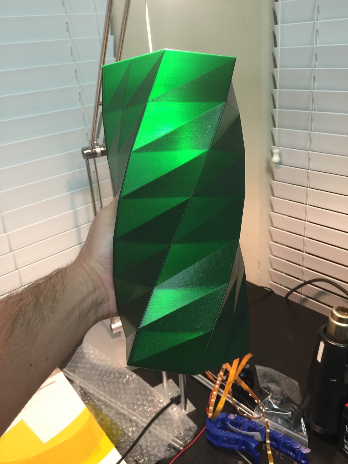
Then I printed a bigger vase out of E3D's EDGE filament:
E3D EDGE filament in green
I love the way the light shines through it and how the geometric shapes create interesting light and dark areas. I thought these vases might make a neat lamp so I decided as a test to make the blue PLA vase into a lamp to see how it would look.
I had a couple of these IKEA lamp sockets laying around. They looked perfect for this.
I drew lines from corner to corner to find the center. Then I used a stepped drill bit to drill a big hole. I used a half round file to take the hole out to the final size.
It was a bit of a tight fit getting my hand down in there to tighten the ring on to the lamp base.
I hung it up in the garage just to test. Turn on the lamp and turned off the rest of the garage lights. Amazing!!
Here it is with the garage lights on
I think I'm going to make three similar to this and hang them over the bar in my kitchen. I've been wanting to add more light there and I think something like this would look great.
A few months ago my daughter asked me to print something for her on my 3D printer. I asked her what she wanted and she said "something Minecraft". We started looking at designs on thingiverse and came across a design for a Mincraft ore block. I thought it might be cool to make a night light out of it using Adafruit Neopixel LED strips and an Adafruit Pro Trinket microcontroller to change the colors. I ended up having a bit of scope creep on this project and it took way longer than I expected but the end result was pretty neat and I learned some new things. Originally I was just going to program the Arduino to cycle through colors but then I came across the Adafruit Bluefruit LE breakout board and realized it would be fairly easy to add BLE control to the project. In the end this was the most involved Arduino coding project I've done so far. At the bottom of this post there are links to download the 3D models and Arduino code if you want to build one yourself.
3D Printing
The first step in this project was to 3D print the plastic parts. I printed the cube at 1.5 times the original size which made the final dimensions 105mm on each side. I had to print it with supports for the holes and a brim to minimize lifting from the print bed. It took almost 18 hours to print it. After it was done printing I realized there wasn't good way to attach a base to the cube (other than glue) so I used OpenSCAD to add recessed corner posts with screw holes and reprinted it.
I used FreeCAD to design an insert that fits inside the cube. The LED strips sit in the channels and the electronics go in the square opening on the bottom.
Diffuser panels
With the 3D printing done the next step was to make some diffuser panels to go on the inside of the cube so you don't see the individual LEDs. I considered 3D printing the diffusers out of natural filament but that would have taken several hours. I had some scrap plexiglass in the garage so I cut out pieces to fit the top and four sides. I sanded both sides of the plexi with 80 grit sandpaper to make them opaque. I tested the diffusers with the LED flash light on my iPhone and they seemed to work pretty well.
Assembling and wiring the insert
The first step in assembling the insert was to cut and solder the LED strips. Adafruit Neopixel LED strips can be cut with scissors. There are cut lines printed on the strip between each LED. I designed the insert to fit three LEDs on each side and five on top. To minimize the number of jump wires I would need to solder I cut three strips and bent them around the edges.
I used the tip of my soldering iron to melt holes for the wiring to pass through to the center of the insert. With the strips set in place I soldered jumper wires onto the end of the LED strips, passing the wires through the holes so the wires were on the inside of the insert and not getting in the way of the LEDs. Then I used hot glue to attach the LED strips to the insert. The Neopixels are addressed by numbers starting with zero for the first LED on the strip so they need to be wired back up as a continuous strip. The strips are also directional so you need to pay attention to the arrows on the strips, wiring them so the arrows all face the same direction. I put a female header on the end of the of the strip wiring so I could plug it into the circuit board.
Breadboarding the control circuit
I hooked up the circuit on a breadboard to test it out before soldering. Controlling the LEDs only requires one digital pin. The BLE breakout board communicates over SPI.
Once I had everything wired up I loaded the Adafruit_NeoPixel strandtest example code to make sure all my LEDs were working correctly.
Soldering the control board
The two main components of the control board are the Pro Trinket microcontroller and the Bluefruit BLE breakout board. I decided to use headers so the microcontroller and BLE chip can be easily replaced if needed. I started with a half-size Adafruit Perma-Proto broad. To make the control circuit as compact as possible I placed the Pro Trinket on one side and the BLE board on the other. To do this I needed to cut the traces for a few holes. I used an X-ACTO to cut and scrape the traces. I used my multimeter to verify there was no continuity.
Cutting the traces on the Perma-Proto board
After cutting the traces I soldered on the headers for the Pro Trinket and the BLE breakout.
Pro Trinket plugged into its headers
BLE board plugged into its header
I finished up the wiring between the microcontroller and BLE board and added some male headers for connecting the LEDs and power input. After that I used a Dremel to cut down the proto-board as small as possible.
Here is the finished control circuit.
Power switch and power input
On the back of the cube I added a barrel connector for power and a small toggle switch. The toggle switch controls the power to the microcontroller and the LEDs. The power cable is routed through a small hole in the white insert.
Assembling all the parts
The insert was secured to the cube with countersunk head 4-40 screws. I added some stick on rubber feet and stuffed the control board in the square opening.
One mistake I made was using too much hot glue to attach the LED wiring inside the square hole of the insert. The extra glue caused the control board to protrude a couple millimeters. Not a huge deal but I would have liked the bottom to be completely flat. I had planned to put a cover on the bottom so I just designed it to account for the protrusion. I fired up FreeCAD again and whipped something up.
The cover was attached with pan head 4-40 screws.
Writing the code
For the Arduino code I started with Adafruit's nRF8001 echoDemo example. It basically does serial communication between the Arduino and an iPhone app.
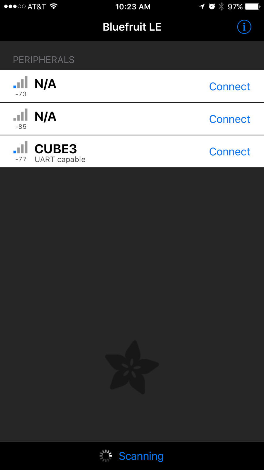
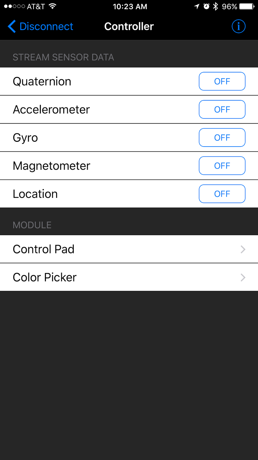
Adafruit also provides a demo iPhone app called Bluefruit LE Connect. The app lets you interact with the BLE breakout board without having to do any iOS development.
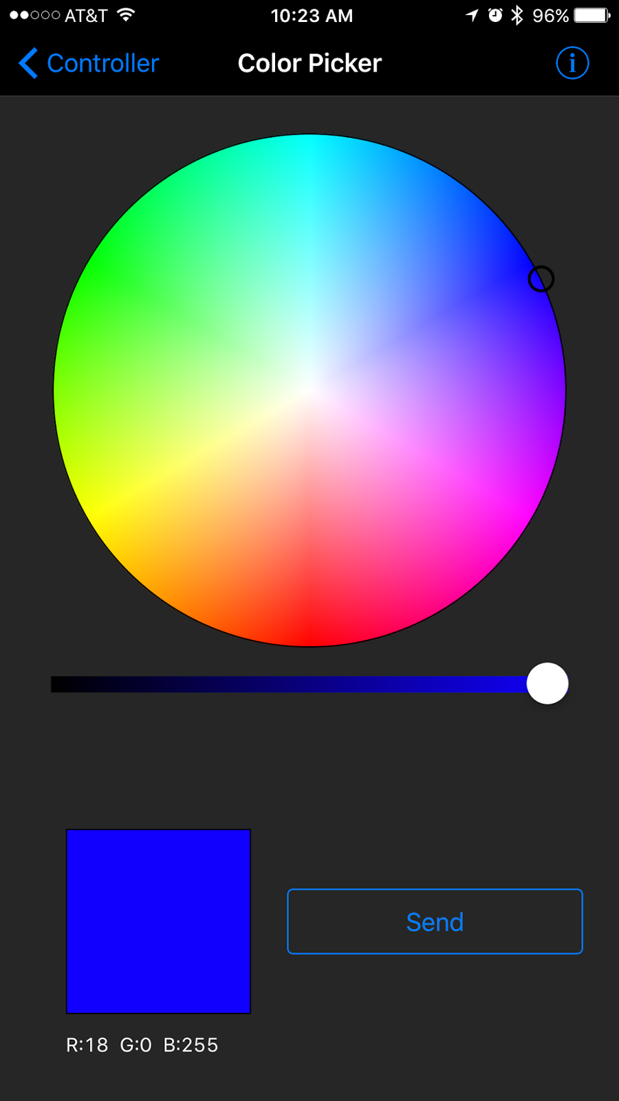
After playing around with the color picker in the iOS app I saw it was sending RGB values formatted like this: !C180255
The exclamation point indicates a command, the next character indicates what kind of command, followed by red/green/blue values. This seemed like a good format for all of the commands I planned to send to the cube. I started planning out all the commands on my whiteboard.
One thing I hadn't worked with before on Arduino boards was EEPROM memory. I understood basically how it worked but hadn't actually used it in a project yet. Turn out to be very straight forward. On the Atmega328P chip there are 1024 possible EEPROM memory locations and you can store one byte of info in each location.
Here are the major features of my Arduino code on the cube:
Set the whole cube to a single color
Set the color of each side individually
Activate animations (Pulse, Rainbow, and Cycle)
Set a new BLE name on the cube and save it to EEPROM
Save the current colors and animation settings to EEPROM
Read settings from EEPROM on start up
Set base values in EEPROM for new boards
Flash green to confirm commands
I won't go into great detail about the code itself. You can read through it here if you would like. I tried to comment it well. I'm sure it can be improved quite a bit so feel free to send suggestions or pull requests.
Demo
Here is a (long) video showing most of the functions of the cube
Download links
As promised here are links to download everything if you want to make one of these yourself. The Fritzing diagram lists all the parts needed.
ABS plastic can be sensitive to air currents while printing. A cool gust of air from an A/C vent, open window or ceiling fan can cause a part to warp or lift from the bed. Living in Texas we have the ceiling fan running in our home office all the time so it was a must for me to build an enclosure for my Printrbot Simple Metal printer. I also wanted to keep my 3D printer from getting dust build up on it. I've read that dust can get in the hot end and cause clogs.
I started with a wooden platform made out thin hardboard on top of MDF. Then I built the upper part of the enclosure out of plexiglass and aluminum channel. I purchased the plexi and aluminum channel from Lowes. The aluminum channel is 1/16" x 3/4" x 3/4". I bolted the whole thing together with #8-32 screws. The build chamber dimensions are 15"H x 20"W x 22"D.
I 3D printed some screw down feet for my Printrbot so it doesn't move around inside the cabinet. You can download the design for the feet here: http://www.thingiverse.com/thing:724909
The whole front of the enclosure is a hinged door. Magnetic door catches keep the door closed.
The top of the cabinet is also hinged and can be opened.
My Printrbot has a heated print bed so it uses an ATX power supply from a computer. It has a bunch of extra wires that aren't used by the printer so I made a hollow area underneath to hide all the extra wires.
The power supply is mounted in the corner so it takes in and vents air outside of the enclosure so it doesn't overheat.
I made a spool holder out of a 6" Lazy Susan bearing and a piece of plywood. I put a 3/8" carriage bolt in the center of the spool holder turnable which is used to secure the filament spool to the holder. I used some #6-32 stand-offs and #6-32 screws with the heads cutoff to allow the turntable to sit an inch above the lid so it can rotate. This also allows the turntable to be lifted off when the top lid needs to be opened.
Here is a more detailed shot showing the path of the filament into the cabinet. I drilled a .25" hole in the top panel.
Next I added LED light strips around the top of the cabinet to light up the inside. The strips are power by +12vdc so I was able to hook them up to the Printrbot ATX power supply. The lights turn on when the printer is powered up.
Here is the printer in action inside the cabinet:
There one thing I'm still working on. I put an exhaust fan in the upper right corner of the back wall of the cabinet. I don't want the cabinet to get too hot inside but I also don't want the fan to run all the time or run at full speed so I'm designing a small circuit that controls the fan speed based on the temperature inside the cabinet.
UPDATE 2015-08-18
I mounted my OctoPrint print server running on a Raspberry Pi to the side of the cabinet. I also added a 20x4 character LCD display that shows useful info about the printer.