After I upgraded my Printrbot with the Matrix Precision X,Y and Z upgrades I now have a build volume of 8"x8"x10" (203mm x 203mm x 250mm). The first thing I tried printing with the expanded print volume was a couple vases.
First out of some junk PLA I'm trying to get rid of:
Blue PLA filament
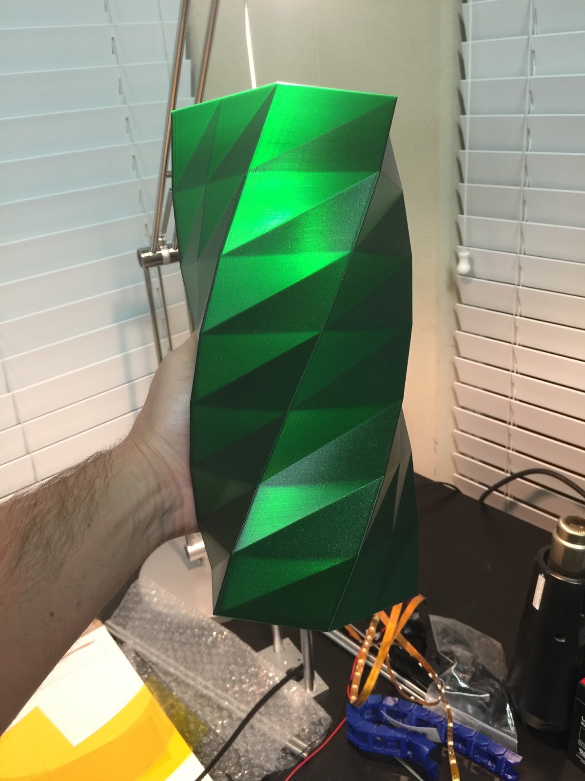
Then I printed a bigger vase out of E3D's EDGE filament:
E3D EDGE filament in green
I love the way the light shines through it and how the geometric shapes create interesting light and dark areas. I thought these vases might make a neat lamp so I decided as a test to make the blue PLA vase into a lamp to see how it would look.
I had a couple of these IKEA lamp sockets laying around. They looked perfect for this.
I drew lines from corner to corner to find the center. Then I used a stepped drill bit to drill a big hole. I used a half round file to take the hole out to the final size.
It was a bit of a tight fit getting my hand down in there to tighten the ring on to the lamp base.
I hung it up in the garage just to test. Turn on the lamp and turned off the rest of the garage lights. Amazing!!
Here it is with the garage lights on
I think I'm going to make three similar to this and hang them over the bar in my kitchen. I've been wanting to add more light there and I think something like this would look great.
The guys at Itead Studios are running an Indiegogo campaign for a couple new smart home products they developed called the Sonoff and the Slampher. Itead asked me to write up a review in exchange for some free samples. I received the samples a few weeks back and they sat on my desk for a few days while I thought about what exactly I would do with them.
What are they?
Parts I received from Itead
When Itead was first talking with me about doing a review they kept calling the devices 'wifi switches' which really confused me. I thought they were talking about some sort of networking equipment. Once they sent me a link to the Indiegogo campaign I finally understood. They are smart home switches for controlling lights and appliances. They reminded me a bit of the old X10 systems but the difference with the Itead devices is they connect to your wifi network. They also have the ability to be controlled and show you current state of the device on your smart phone even when you are away from the house. The devices check in with Itead's cloud service to update their state and check for commands. The devices respond to smart phone commands nearly instantly which is pretty impressive.
Smartphone app
Itead has an iPhone and Android application called eWeLink for controlling and configuring the devices so I had to install that before I could setup either of them. Installing the app was easy enough but I ran into trouble trying to create an account. Elsie from Itead said the iOS app was very new and had a few bugs to be worked out. To create an account all you have to do is enter your mobile number, a password for your new account and touch 'Send verify code'. Itead is then supposed to send an SMS message with a verification code. I got an error when trying to do this. After a few e-mails back and forth with Itead they fixed some things and I was finally able to create an account. I believe they have these problems worked out now so it shouldn't be a problem for anyone else.
eWeLink in the app store
Creating an account
Error :(
Adding devices
Initially I had a little trouble adding devices. This was due partially to the instructions in the iPhone app being a bit sparse and partially because I had this thought in my head that I was trying to connect to a bluetooth device. I e-mailed Elsie again and she replied with some better instructions. I now realized the devices are strictly wifi. In pairing mode the device creates a temporary wifi network. You connect your phone to this temporary wifi network and then use the app to configure the device.
Control button and Status LED locations
To put the device into pairing mode (and create the temp wifi network) press down on the control button for several seconds and release. The status LED will begin blinking rapidly indicating it is in pairing mode. Then join the wifi network named 'ITEAD-xxxxxxxx'. After that you go to the eWeLink app and add the device. The pairing process is just giving the device your wifi network SSID and password so it can join your network.
Using the Slampher
I decided to try out the Slampher first since all I had to do was screw it into a light socket. I installed it in my bedside lamp. One issue with the Slampher is the height. I suppose it would will work fine with some lamps and not so great with others. Lamps with tall shades will probably work best. Once you install the Slampher you have to stop using the normal power switch on the lamp and start using the control button on the device instead (or the smartphone app). It is convenient they still give you the option to control the lamp locally in addition to the smart functionality.
After adding the Slampher to my device list in the smartphone app I configured two timers. One that corresponds with my weekday alarm clock at 6am and another at 8pm every night. Timers are easy to configure and have flexible options that allow everyday, weekday, weekend or custom timers.
Custom Timer
Lamp Off
Lamp On
The weekday morning timer is very effective at getting me up. Every morning I yell at my lamp "OK I'm up already!".
Using the Sonoff
The Sonoff is design to be used with an appliance of your choosing unlike the Slampher which is specifically for a light socket. It's a little more difficult to use because you have to do some wiring to utilize it. I didn't want to cut into the cord of any of my devices so I settled on cutting up an extra extension cord making it into a 'smart' extension cord :-). Make sure everything is unplugged before you go cutting into wires. K thx.
I cut the extension cord in half and stripped the ends of the wires.
I tinned the ends of the wires with my soldering iron to make sure I didn't have any stray strands that could short out.
The wires slide into terminal blocks and are tightened down with small flat blade screwdriver.
The samples I received didn't come with screws for the green cover plates. I think the covers are fairly important because you don't want exposed mains voltage! I had some screws on hand to attach the covers. I imagine the final product will come with screws.
Finished. My 'smart' extension cord.
I decided to use my new smart extension cord to control the lights on my fish tank. I set a timer to turn off the lights at 10:30pm and back on at 6am.
Happy fish
Overall Impression
The devices work as advertised but the iOS app needs some work. Like I mentioned earlier I had trouble creating an account and the english translations for some things are awkward. The 1.0.5 version has improved the translations dramatically. The first version of the app I used still had Chinese characters for some items. I've been using the timers for a little over a week now and they have consistently worked. I really like the convenience of being able to turn off my bedside lamp from my phone at the breakfast table if I forget to do it before heading downstairs. The pricing in their Indiegogo campaign is significantly cheaper than comparable devices from other manufacturers.
A downside to these devices is that they only work when you have an internet connection but I think for most people who would want to use a 'smart' device that wouldn't be problem. A bigger concern I have is that these devices are completely reliant on Itead's cloud service for smartphone control and the timers. If that service is shutdown these devices become bricks.
The Sonoff and Slampher are a good start but I think a device that could replace a wall switch would be the most useful to me. Something like this:
A few months ago my daughter asked me to print something for her on my 3D printer. I asked her what she wanted and she said "something Minecraft". We started looking at designs on thingiverse and came across a design for a Mincraft ore block. I thought it might be cool to make a night light out of it using Adafruit Neopixel LED strips and an Adafruit Pro Trinket microcontroller to change the colors. I ended up having a bit of scope creep on this project and it took way longer than I expected but the end result was pretty neat and I learned some new things. Originally I was just going to program the Arduino to cycle through colors but then I came across the Adafruit Bluefruit LE breakout board and realized it would be fairly easy to add BLE control to the project. In the end this was the most involved Arduino coding project I've done so far. At the bottom of this post there are links to download the 3D models and Arduino code if you want to build one yourself.
3D Printing
The first step in this project was to 3D print the plastic parts. I printed the cube at 1.5 times the original size which made the final dimensions 105mm on each side. I had to print it with supports for the holes and a brim to minimize lifting from the print bed. It took almost 18 hours to print it. After it was done printing I realized there wasn't good way to attach a base to the cube (other than glue) so I used OpenSCAD to add recessed corner posts with screw holes and reprinted it.
I used FreeCAD to design an insert that fits inside the cube. The LED strips sit in the channels and the electronics go in the square opening on the bottom.
Diffuser panels
With the 3D printing done the next step was to make some diffuser panels to go on the inside of the cube so you don't see the individual LEDs. I considered 3D printing the diffusers out of natural filament but that would have taken several hours. I had some scrap plexiglass in the garage so I cut out pieces to fit the top and four sides. I sanded both sides of the plexi with 80 grit sandpaper to make them opaque. I tested the diffusers with the LED flash light on my iPhone and they seemed to work pretty well.
Assembling and wiring the insert
The first step in assembling the insert was to cut and solder the LED strips. Adafruit Neopixel LED strips can be cut with scissors. There are cut lines printed on the strip between each LED. I designed the insert to fit three LEDs on each side and five on top. To minimize the number of jump wires I would need to solder I cut three strips and bent them around the edges.
I used the tip of my soldering iron to melt holes for the wiring to pass through to the center of the insert. With the strips set in place I soldered jumper wires onto the end of the LED strips, passing the wires through the holes so the wires were on the inside of the insert and not getting in the way of the LEDs. Then I used hot glue to attach the LED strips to the insert. The Neopixels are addressed by numbers starting with zero for the first LED on the strip so they need to be wired back up as a continuous strip. The strips are also directional so you need to pay attention to the arrows on the strips, wiring them so the arrows all face the same direction. I put a female header on the end of the of the strip wiring so I could plug it into the circuit board.
Breadboarding the control circuit
I hooked up the circuit on a breadboard to test it out before soldering. Controlling the LEDs only requires one digital pin. The BLE breakout board communicates over SPI.
Once I had everything wired up I loaded the Adafruit_NeoPixel strandtest example code to make sure all my LEDs were working correctly.
Soldering the control board
The two main components of the control board are the Pro Trinket microcontroller and the Bluefruit BLE breakout board. I decided to use headers so the microcontroller and BLE chip can be easily replaced if needed. I started with a half-size Adafruit Perma-Proto broad. To make the control circuit as compact as possible I placed the Pro Trinket on one side and the BLE board on the other. To do this I needed to cut the traces for a few holes. I used an X-ACTO to cut and scrape the traces. I used my multimeter to verify there was no continuity.
Cutting the traces on the Perma-Proto board
After cutting the traces I soldered on the headers for the Pro Trinket and the BLE breakout.
Pro Trinket plugged into its headers
BLE board plugged into its header
I finished up the wiring between the microcontroller and BLE board and added some male headers for connecting the LEDs and power input. After that I used a Dremel to cut down the proto-board as small as possible.
Here is the finished control circuit.
Power switch and power input
On the back of the cube I added a barrel connector for power and a small toggle switch. The toggle switch controls the power to the microcontroller and the LEDs. The power cable is routed through a small hole in the white insert.
Assembling all the parts
The insert was secured to the cube with countersunk head 4-40 screws. I added some stick on rubber feet and stuffed the control board in the square opening.
One mistake I made was using too much hot glue to attach the LED wiring inside the square hole of the insert. The extra glue caused the control board to protrude a couple millimeters. Not a huge deal but I would have liked the bottom to be completely flat. I had planned to put a cover on the bottom so I just designed it to account for the protrusion. I fired up FreeCAD again and whipped something up.
The cover was attached with pan head 4-40 screws.
Writing the code
For the Arduino code I started with Adafruit's nRF8001 echoDemo example. It basically does serial communication between the Arduino and an iPhone app.
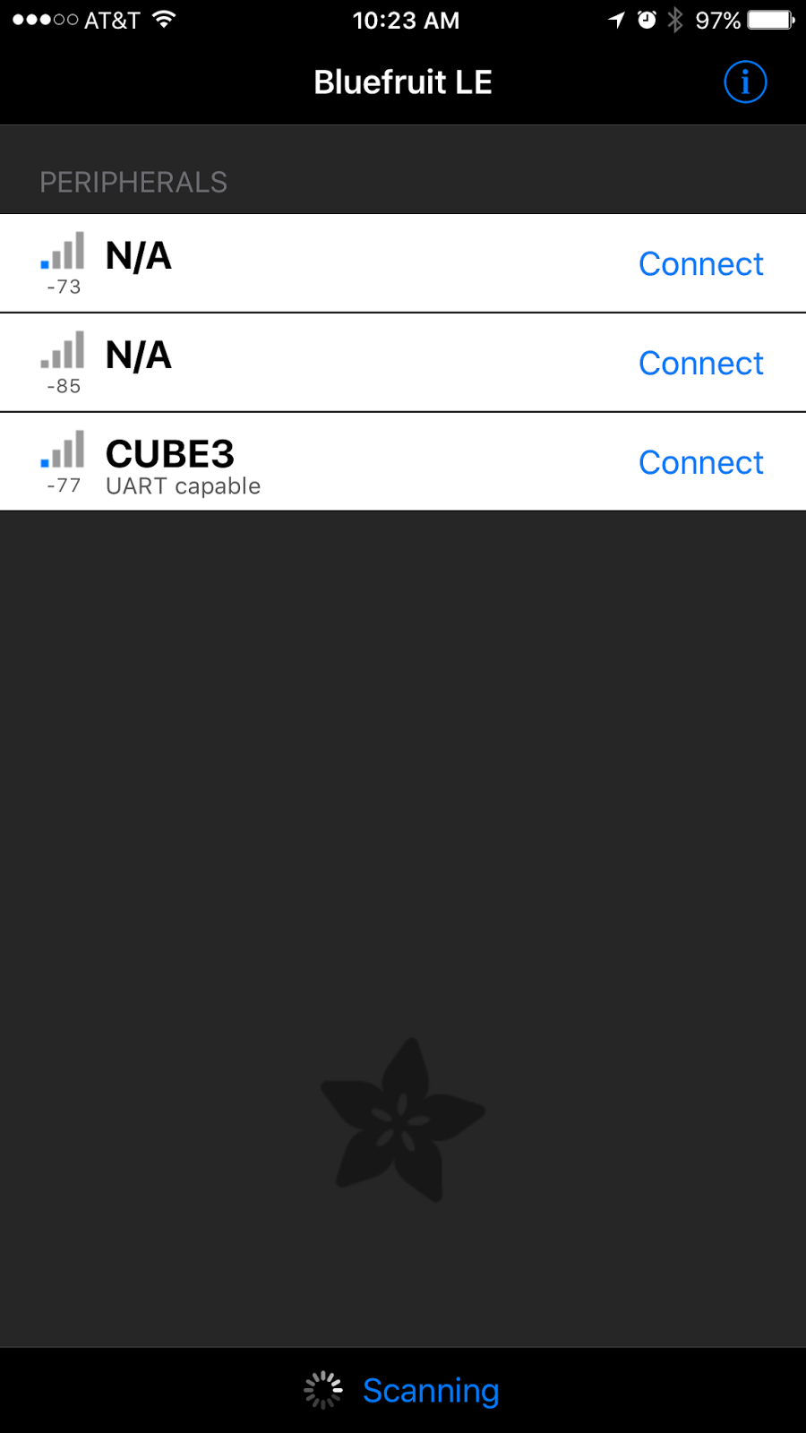
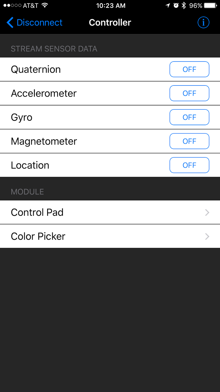
Adafruit also provides a demo iPhone app called Bluefruit LE Connect. The app lets you interact with the BLE breakout board without having to do any iOS development.
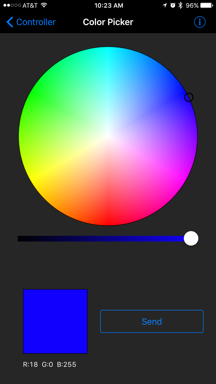
After playing around with the color picker in the iOS app I saw it was sending RGB values formatted like this: !C180255
The exclamation point indicates a command, the next character indicates what kind of command, followed by red/green/blue values. This seemed like a good format for all of the commands I planned to send to the cube. I started planning out all the commands on my whiteboard.
One thing I hadn't worked with before on Arduino boards was EEPROM memory. I understood basically how it worked but hadn't actually used it in a project yet. Turn out to be very straight forward. On the Atmega328P chip there are 1024 possible EEPROM memory locations and you can store one byte of info in each location.
Here are the major features of my Arduino code on the cube:
Set the whole cube to a single color
Set the color of each side individually
Activate animations (Pulse, Rainbow, and Cycle)
Set a new BLE name on the cube and save it to EEPROM
Save the current colors and animation settings to EEPROM
Read settings from EEPROM on start up
Set base values in EEPROM for new boards
Flash green to confirm commands
I won't go into great detail about the code itself. You can read through it here if you would like. I tried to comment it well. I'm sure it can be improved quite a bit so feel free to send suggestions or pull requests.
Demo
Here is a (long) video showing most of the functions of the cube
Download links
As promised here are links to download everything if you want to make one of these yourself. The Fritzing diagram lists all the parts needed.