I bought a green 7-Segment Display w/I2C backpack and a 2.2" color TFT LCD display from Adafruit to experiment with.
|
|


The backpack on the 7 segment display allows it to be controlled by the Arduino using the I2C protocol (also called Two Wire Interface). Without the I2C backpack you would have to directly control all eight segments of each number which would use up all the pins on the Arduino or you would have to figure out some other method which would probably end up being very similar to what Adafruit did. Each Arduino model has certain pins that are used for I2C. On the Uno pins analog 4 and analog 5 are used for this purpose. See the Wire library page for more I2C info.
What is a VSS?
Most modern computer controlled cars since the late 1990's have a sensor called a VSS or Vehicle Speed Sensor. The location of the sensor varies but they all do the same thing which is count the number of times some part of the drive train rotates. On my car the VSS is in the transmission. The output of the VSS is some number of pulses per mile in a 5 vdc square wave signal. The first step in this project was to find out how many pulses per mile my VSS puts out. This number varies from car manufacturer to car manufacturer and sometimes model to model. I found a company that makes aftermarket cruise control systems and their installation manual contained a list of cars and VSS pulses per mile. The pulses per mile value can range from 2000 all the way up to 38600. The VSS on my car puts out 4000 ppm which seems to be a common value but you must find out the correct value for your particular vehicle otherwise the readings will be incorrect. You can also consult their installation manual for the location of the VSS signal wire. It is important that you only tap into the VSS wire and not completely interrupt it. The engine and transmission computers use this signal as well.
Time for some math
So now I know my VSS puts out 4000 pulses per mile. Next I need to figure out how to convert that into miles per hour. After looking at some example code on how to measure pulses I decided I would count the VSS pulses for one second. With that info I could then convert the pulse count into mph. First I converted one hour (the hour from miles per hour) into seconds which is 3600. Then divide the number of pulses per mile by the number of seconds (4000/3600). Then you divide the number of pulses counted on the sensor by that value. Here is my final formula:
miles per hour = pulse count/(VSS pulses per mile/time period)
Building the prototype
I started with an Arduino Uno and an Adafruit Protosheild. I hacked up an old USB cable to connect the 7-segment display. A USB cable is perfect for this. Two wires for the I2C and two larger gauge wires for power and ground. I cut off the ends of the USB cable and stripped each of the wires. I tinned the wires with solder so I could plug them directly into the bread board and added some heat shrink tubing for strain relief. Here is a Fritzing diagram of the wiring:

- Connect 'C' (CLK) on the display to Analog #5. (Leonardo Digital #3, Mega digital #21)
- Connect 'D' (DAT) on the display to Analog #4. (Leonardo Digital #2, Mega digital #20)
- Connect GND on the display to common ground
- Connect VCC+ on the display to power +5V
- VSS sensor on the vehicle connects to Digital #5
- Analog #0 is used to measure a Photocell (Light Dependent Resistor)
Here is how the wiring looks
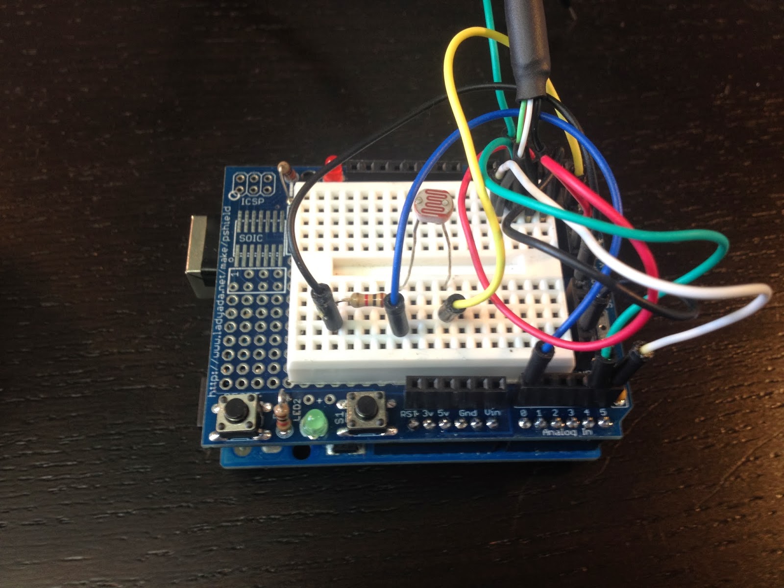

After I tested it at night I decided to add a photocell (Light Dependent Resistor) to control the brightness of the display. It took some tweaking to get the brightness changes just right. Initially the brightness of the display fluctuated with every street light I passed. I changed the code to use an average of 30 light level readings. That way the brightness changes slowly.
Here is how it looks in my car during the day.

and at night

The github repo is here https://github.com/matt448/arduino/tree/master/Speedometer_7seg
The code for the hardware pulse counting section came straight from example 18.7 in the Arduino Cookbook. My understanding of how this works is: the ATmega chip has a few hardware timers. This code uses a timer on Digital #5 on the UNO. The TCCR1B part of the code sets bits on that timer to configure it to count pulses. The code then waits for one second and reads how many pulses were stored in the hardware counter. Then the hardware counter is reset to zero for the next loop. Keep in mind this code is written specifically for an Arduino Uno. It would need to be modified to work with other boards.
Here is the current version of the code in a gist.
I made a quick little cardboard housing for the 7-segment display to shield it from the sun.
After I tested it at night I decided to add a photocell (Light Dependent Resistor) to control the brightness of the display. It took some tweaking to get the brightness changes just right. Initially the brightness of the display fluctuated with every street light I passed. I changed the code to use an average of 30 light level readings. That way the brightness changes slowly.
Here is how it looks in my car during the day.
and at night
The code
The github repo is here https://github.com/matt448/arduino/tree/master/Speedometer_7seg
The code for the hardware pulse counting section came straight from example 18.7 in the Arduino Cookbook. My understanding of how this works is: the ATmega chip has a few hardware timers. This code uses a timer on Digital #5 on the UNO. The TCCR1B part of the code sets bits on that timer to configure it to count pulses. The code then waits for one second and reads how many pulses were stored in the hardware counter. Then the hardware counter is reset to zero for the next loop. Keep in mind this code is written specifically for an Arduino Uno. It would need to be modified to work with other boards.
Here is the current version of the code in a gist.
Results
I tested my new speedometer against the GPS and it was right on the money. It also reacts quite a bit faster than the GPS and it works inside a parking garage unlike the GPS. I have been using it for about a month now and it works great. The only negative I have found is the display isn't readable when the sun is shining directly into it which isn't very often because of the housing. I'm looking into other display options now that I have something that works. VFD displays seem like a good option. I'm also still tinkering with the 2.2" TFT display. Here is a video of the speedometer in actionNext steps
I am planning to solder all the connections on a piece of perfboard that I have turned into a shield of sorts. I'll need to put it in a box and tuck it some where in the dash. Currently I am powering the unit with a 12volt to USB power supply which is plugged into a cigarette lighter jack. I might take that apart and package the guts of the power supply with the Uno.

Hi Matthew, Thank you for the detailed post. I'm going to make something like this for my car as well. Could you please tell me where did you get VSS signal from? Did you get it directly from VSS wire or from ECU pin? I have a 95 Toyota Trueno.
ReplyDeleteI tapped into the VSS wire just before the ECU. In my Toyota the ECU is below the dashboard on the passenger side so it was easier to get access to the wire there than at the VSS sensor in the engine compartment.
DeleteHi Matt, I was able to get your code working along with a RPM meter on Proteus simulator.
Deletehttps://dl.dropboxusercontent.com/u/28031454/simulator.jpg
I got a service manual of my car and will be able to tap into VSS pin soon. btw thank you for the reply.
Hello,
ReplyDeletewhich voltage does the VSS signal have. Can I connect it directly to the arduino or is a resistor or voltage divider needen?
Regards
Bastian
On my Toyota the VSS has a 0-5v square wave output so I was able to connect it directly to the Arduino. I believe most modern vehicle sensors use a 0-5v output. The safe thing to do is measure it with a voltmeter or scope to be sure. An even safer thing to do would be to put an opto-isolator between the VSS and the Arduino.
DeleteHi, nice job, there is son way to auto-calc the vss of the vehicle?
ReplyDeleteOne way to do that would be to drive exactly one mile (or one kilometer) and count the number of pulses and then store that value. You would need some sort of flash storage to hold that data and then read it on startup. You could press a button to start counting pulses and then press it again to end the counting.
DeleteI gotta thank you. Your post has been instrumental in my fuel gauge and speedometer project.
ReplyDeleteI didn't even know the arduino had a pulse counter. Without it, I would have given up from frustration and shelled out for one of the $400+ price-gouged clusters on ebay (My cluster has a common defect that Nissan refuses to acknowledge or provide an OEM replacement. Knowing that, junkyards treat them like gold).
And bonus points for making an old truck look futuristic.
I have cut out most of the code on my project so that it prints to the seial monitor. Everytime I connect anything to PIN5 I get random readings. Got any ideas?
ReplyDeleteWhat Arduino board are you using?
DeleteNice work. Quick tip.
ReplyDeleteThis:
if(brightness > 15){
brightness = 15;
}
if(brightness < 1){
brightness = 1;
}
Can more easily be written as:
brightness = constrain(brightness, 1, 15);
Thanks for the tip!
DeleteIm using a redBOARD from Sparkfun which emulates a UNO (https://www.sparkfun.com/products/12060).
ReplyDeleteSince my previous post I have grounded the VSS and that has stabalized the signal, but it is still offset by a 54mph reading that the board is instatly reading when connected to the VSS that is energized. I Have the VSS out of the car on my desk powered by an external powersupply when I am doing this, and turn it with a drill to get the pulse.
The lead to the board in my opinion is acting like a antenna, but i dont know if it is because of my board(redBoard trigger assigment vs your trigger assignment) or if it is because of the PWM signal ingeneral. I know in the repair manual that the PWM signal is shielded.
Either way, I get a 54 reading when I connect a lead to the board and am not connected to the VSS, as well as when connected to the VSS when grounded.
The other day I was working with my board and I had a jumper wire plugged into pin5 and not connected to anything else. When I brought my LED work light near the jumper wire the speed would show 54mph. I think it is acting like an antenna and it's picking up frequencies emitted by AC powered electrical devices. I don't have any issues when the board is in my car.
DeleteOne other thing, I tried to build this project a second time using an Adafruit Pro Trinket board which uses the same microcontroller as the UNO but I got very erratic readings when trying to use the hardware pulse counter on that board. I built another one using a different UNO and it worked fine. I haven't had a chance to figure out why the Pro Trinket didn't work. You might want to try using a real Arduino UNO and see if the weirdness goes away.
Soooo....I moved downstairs away from my desktop, lamp, and ceiling fan to run the code on the same board and a laptop and the issue went away....I now get a constant 0. I think there is just too much noise in the previous location.
ReplyDeleteNow onto calculating a RPM signal.
Thanks for the code...I will be catching up on your other exploits as I plan to digitize my dash.
I'm driving a 98 crown vic
ReplyDeleteYou think I could plug directly into the speedometers back and get a reading there?
Looks like there is a VSS signal wire on the instrument cluster connector. I have no idea what the voltage is though. I would recommend verifying with at least a multimeter or scope if possible.
Delete(Please excuse all of my newbie ignorance)
DeleteYes, for this model car, it appears to work. Last night I wired it, today I tested it with a volt meter. 4 wires lead to the back {from memory} they read - battery s b g. I used a cat5 and connected 4 wires to the retaining clips and led the cable out the center console. Speedo needle seemed fairly non responsive on start up. Later had to go to corner store and five minutes of driving I noticed that the needle was responding, and somehow seemed steadier ? (Note my gas needle also seemed to not drop in large incriminates as it used to.)
Anyhow, testing multiple configurations,/combinations of the four leads, I've found my fluke is giving accurately repeatable results on its %hz selection.... With car off, it shows slow rythmic spikes showing 250ish.... Actually there seems to be nothing rhythmic about it. Numbers all over the place. (I'm lost. I'm not particularly looking for an answer but for others sake I'll post a vid and link for others and to be addressed if desired.} Anyway, repeatedly, while in motion, I receive consistent numbers (I'll post another video of those numbers too for others)
I'll work on a translator for arduino later correct
The dash leads I connected to are
S(- on meter
G (+ on meter
These, (after posting my video) seem like they are more likely the correct readings a vss would output, correct ?
1998 Mercury Grand Marquis LS ( Ford Victoria )
I can't upload the video yet.
ReplyDeleteSeems to be a 2.15 ratio for mph to measured hz cycles. A near 10x conversion of measured v. Seems closer to 10x when judging v against gps reading
Is Late night here. Cars been sitting. Off.
ReplyDeleteIt's about 10 deg f colder in the air .
Voltage is now reading .7 more than before. Seems to slowly drop as i run the engine. Can't drop the difference more than .5.
Hz cycles remain the same 2.15 ration.
I think there is most people's answer.
Now, rotiometric, a new term for me.
Must understand this before safely having my Arduino measure this hz cycle / pwm rate.
High voltage spikes can damage the arduino.... but seems pretty safe to say, as long as i don't go hundred miles power hour i should remain at around our below 10 To 12 volts .
More studing
So much to dig through .
Voltage divider (plus a capacitor? )
In the Morning
According to this manual you should be seeing 8000 pulses per mile from your VSS: http://www.rostra.com/manuals/Form4428L.pdf
DeleteIn the code you will need change the variable pulsesPerMile from 4000 to 8000.
Something else you can do for testing is buy a speed sensor and turn it with a drill. That way you can work at a desk instead of trying to watch a meter while you drive. You can get a VSS for your car from rockauto.com for about $15 bucks.
To keep voltage spikes and noise from reaching your Arduino you can use an optoisolator. Check out this document: http://playground.arduino.cc/uploads/Learning/Level_shifting_4_arduino.pdf
I disappeared for a bit.
ReplyDeleteHad family health issues other projects, and a mysterious vibration in my car tearing apart gaskets and had to walk, as i repaired. But, I'm back ontop and she's purrin.
Just to touch base, and i don't know why, but yeah, i tried to measure the pulses as voltage but Quickly saw why that wouldn't work as it cycled and flashed through my range set. Then decided to average it, and then said... wait a second, there's Matthew. i caught the 8000 online and your 4000 snipped out your pulse measurement section and slipped it in my code. (Btw i just volt div with two 10ks on each line and tapped in) All very comprehensive but i dropped the 7 dig cause I'm driving entire cabin rgb ambient lighting. At a light, my doors glow and flicker like fire, illuminating my face, then in motion it ramps through a spectrum and around. .. 88mph out stays flashing bright bright white ....
I feel very confident about your translating section of code BUT, I'm glitching, i think somewhere in my own code. Just adding yours has forced only my blue lights on mid range. I think it's just my code. Looking now. All i can say is blue channel is in pin 11, then red 10 green 9. I saw the cs11 bit in your code but it doesn't appear to actually have any thing do with pin 11?
I dunno. Still working it out
I think I can confirm a glitch concerning the timers and pwm on my color channel pins 9 10 and 11. found this.
ReplyDeletethe problem-----The problem is that when I use timer1, PWM on pin 9 and 10 is dead. Pin 9 is the worst one, if I try to use it as analogWrite, arduino will stall. If I use pin 10, arduino will ignore any analogWrite request. It doesn't affect pin 3 and 5. however, if I use timer0, i think it was pin 11 and 3 will be affected in the same way. -----
the illumination -------- this is expected. if you look at the atmega 328 pin map: http://cdn3.raywenderlich.com/wp-content/uploads/2013/06/atmegaPinMap.jpg
you will see that timer 1 involves oc1A and oc1B, which are connected to pwm pins 9 and 10. timer0 involves oc0A and oc0B, tied to pins 5 and 6, and timer 2 has the same relationship to pins 3 and 11 --------
hey, at least I can be even more confident our codes are fairly sturdy on their own LOL. gotta love it.
I will work around this mess. Good times
if i switch to timer0 it should solve my problem without having to rewire anything, if I'm not mistaken.... except for the input into pin 5....... I think. that can easily be rerouted.
ReplyDeletethe internal timers mentioned here are new to me. actually its all new to me, in general.
Hi Matt,
ReplyDeletecan you help me coding with another display without light sensor?
display i bought,
Grove - 4 Digit Display is 7-SEG LED tm1637
Hi, I received your e-mail. I'll try to take a look in the next couple days.
DeleteHello, Please excuse my complete lack of knowledge and what may come across as stupidity. I am completely new to Arduino and know almost nothing about programming etc. However I am wanting to build a speedo for a custom motorcycle I am building and this looks about right. I like the idea of the LDR to control brightness. This is my (possibly very silly) question. What resistance value of LDR have you used?
ReplyDeleteAlso my second question. I am wanting to swap the VSS signal for a magnetic read switch type sensor. If I took a 5v supply from the Arduino board and sent it to one side of the switch, then the other side back to pin #5 would this have the same effect?
Thanks in advance.
Not a silly question at all. The LDR I used has a resistance of 200KΩ in the dark to around 10KΩ in the light. I didn't explain much about the LDR circuit in this post. I'll see if I can update it with a little more detail.
DeleteYour idea for the reed switch might work but I have a couple concerns. First, I'm not sure how clean of a signal you will get from it because it has a metal contact that physically opens and closes. There may be some bouncing that would turn into false readings. My second concern is how fast the reed switch can open and close. It may work fine at slower speeds but at 60 mph it might not be physically able to open and close fast enough to catch every pass of the magnet. A good solid state alternative to a reed switch is a hall effect sensor. Something like this: https://www.adafruit.com/products/158
It does the same thing but it doesn't have any moving parts.
In the code you will need to tune the pulsesPerMile value. That value is exactly what it sounds like. It's the number of pulses the board receives after traveling exactly one mile. Might take some experimentation or math calculations.
Hi Matt, thanks for your reply.
DeleteYes please a little more info on the LDR circuit would be great.
I see what you are saying about the read switch. I never knew you could get something like that hall effect sensor, that's probably a safer option. I had planned on using a sensor from a cycle computer, I have a cycle computer on another motorcycle and it seems to work well, I wonder if they use something more like this.
I should be able to calculate the pulses per mile by working the math based on the circumference of my front wheel, how many times it needs to rotate to travel 1mile.
Do you think this circuit could be expanded to log milage like an odometer?
Thanks again.
The microcontroller on the Arduino has built in non-volatile memory called EEPROM that is used to store data when the board is off. You just have to be a bit conservative on how you use it. The chip manufacturer (Atmel) says the EEPROM is good for 100,000 write/erase operations. In real world testing a lot of people are actually getting about 1,000,000 write/erase operations before they start seeing errors in the memory. But even if you updated EEPROM after every mile that's still 100,000 miles which I'm guessing a custom motorcycle probably doesn't see that kind of mileage. The Arduino Uno has 1024 bytes of EEPROM memory. Each byte can store a value between 0 and 255. You just have to come up with a method to store your mileage number in those bytes. Check out this link for more info: https://www.arduino.cc/en/Reference/EEPROM
DeleteAnother option is to use an SD card. Something like this: https://www.adafruit.com/products/254
SD cards usually have a higher write/erase limit and can store a lot more data.
I used Oled 128x64, it has really fast refresh rate. I2c only requires 4 wire. Refresh rate doesn't drop at winter season
ReplyDeleteFound it. Ford vic vss pulses, 18000 pulses.
ReplyDeleteI pushed the numbers around and thought 2.2_ was odd. Noticed my mph displayed was roughly. /2 off. Fought to find the balance, and just added the two together which resulted in a nice even 5. The only thing, besides bending time and space was to bend the 8000... toward 18000. Now it works like a charm
Awesome! Glad to hear you figured it out.
DeleteThis comment has been removed by the author.
ReplyDeleteAny chance you can post the code for the tft screen?
ReplyDeleteNice job, but do you have a TFT version of this with pulse?
ReplyDeleteI want to use is on my own Toyota :)
https://www.youtube.com/watch?v=cSuxPn8sJqs
DeleteGood evening Matt.
ReplyDeleteCan you help me I encoded with a different display without light sensor?
Display module 0.56 "yndykator DESYATYCHNAYA POINT RED RED LED light-emitting diode screen semysehmentnыy 4 Razriad TM1637 RobotDyn.
Thank you.
Sincerely, Alexander.
Alexander,
DeleteUnfortunately I don't have time right now to help you with this. Good luck with your project.
Hi Matt,
ReplyDeleteIs there any way to get the program to update quicker than 1 second intervals?
Thanks,
Paul.
I've been thinking about this myself. One second does seem a bit slow now that I have been using it for a while. I think 250ms might be good. I'll have to take a look at the code. Shouldn't be too hard. Just have to adjust the math. The samplePeriod variable needs to be set to 250. I think a value on line 32 needs to be adjusted as well.
DeleteHi matt, I don't expect any help, I just wanted to say, after my mercury grand marquise blew up into a FIRE BALL FROM HELL a FULL year ago,(nothing to do with wiring btw) that I'm finally back. Got an old 98 dodge ram 1500 I've just piped into and I'm getting a flow. using this code again, perhaps I'll have better luck this time. Thanks for all you've done. I'll keep you posted
ReplyDeleteOh man sorry to hear about your other car!
DeleteHi
ReplyDeleteSorry to be a pain but i decided to try and make a speedo from a rc servo, an arduino uno and a hall switch.
Well as you've probably guessed I've completely underestimated how hard I would find coding something and need some help.
If its something you'd be interested in talking about I'd really appreciate the help if not,no worries and thanks for posting what you made its really informative.
Kind regards
Ted
Hey Matt,
ReplyDeleteThanks for this help. Im nearly there, although being in Australia im am struggling to confirm the correction from mph to kmh. Do you know a resource i could use on this? Currently the resources listed state that the VSS in my 98 Lancer/Mirage should be 4000 pulses per mile. Roughly i believe it should be 6437.2 pulses per kilometer.
One again, thanks for writting this up
Hi Matt, Thank you for posting this project as it is a great help with mine. I am a little confused with something that I hope you can help me with. On line 29 you have const int hardwareCounterPin = 5; and then on lines 104-109 you start the internal timer to record the time between pulses, does it automatically use the signal from pin 5 because the timer that you used is linked to that pin? if so it looks like you used timer 1, but isn't pin 5 linked to timer 0? I am also trying to understand the reason for line 105:bitSet(TCCR1B, CS11); // Clock on rising edge, specifically what the purpose of this is. The only difference in my project is that I am using a photoresistor input that is calibrated to detect either black or white, and blink and led when it detects a white line. When it detects the white line it flashes an LED, I would like the timer to calculate the time between LED HIGH signals, so I can then convert that time into MPH as the pulses per mile. Last, why do you include lines 110-114 where you multiply by 10 and then divide by it later on? I'm a little lost with that.
ReplyDeleteThanks so much
Dhanson,
Delete[ Timer 1 ]
On the Arduino UNO R3 pin 5 is connected to timer 1. I just looked at the UNO schematic to verify.
[ bitSet(TCCR1B, CS11); // Clock on rising edge ]
When the timer is counting pulses it is looking for a voltage change. The pulses I'm counting in this case are a square wave that is alternating between 0 volts and 5 volts. The pulse stays at 5 volts for several milliseconds and then drops back to 0 volts. What line 105 does is tell the counter when to count the pulse, at the beginning of the pulse (rising edge) or at the end of the pulse (falling edge).
[ Multiplying by 10 ]
Floating point math on the Arduino is slow and not accurate. I multiplied by 10 so I could keep 1/10th of a mile accuracy but store the value as an integer.